

5
Installation Clearances
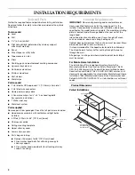
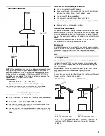
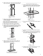
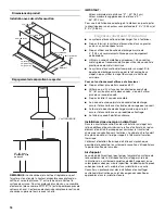
NOTE: The hood chimneys are adjustable and designed to meet
varying ceiling or soffit heights depending on the distance “X”
between the bottom of the hood and the cooking surface. For
higher ceilings an extension kit (Part Number W10197713) is
available, see your dealer. The chimney extension replaces the
upper chimney shipped with the hood.
IMPORTANT:
Minimum distance “X”: 30" (76.2 cm)
Suggested maximum distance “X”: 36" (91.4 cm)
For vented installations, the chimneys can be adjusted for
ceilings between 8'
4¹⁄₄
" (2.55 m) and 9'
4³⁄₄
" (2.86 m).
Venting Requirements
■
Vent system must terminate to the outside.
■
Do not terminate the vent system in an attic or other enclosed
area.
■
Do not use 4" (10.2 cm) laundry-type wall caps.
■
Use metal vent only. Rigid metal vent is recommended. Do
not use plastic or metal foil vent.
■
The vent system must have a damper. If the roof or wall cap
has a damper, do not use the damper supplied with the range
hood.
For the most efficient and quiet operation:
■
Use no more than three 90° elbows.
■
Make sure there is a minimum of 24" (61 cm) of straight vent
between the elbows if more than 1 elbow is used.
■
Do not install 2 elbows together.
■
Use clamps to seal all joints in the vent system.
■
Use caulking to seal exterior wall or roof opening around the
cap.
■
The size of the vent should be uniform.
Cold Weather Installations
An additional back draft damper should be installed to minimize
backward cold air flow and a thermal break should be installed to
minimize conduction of outside temperatures as part of the vent
system. The damper should be on the cold air side of the thermal
break.
The break should be as close as possible to where the vent
system enters the heated portion of the house.
Makeup Air
Local building codes may require the use of makeup air systems
when using ventilation systems greater than specified CFM of air
movement. The specified CFM varies from locale to locale.
Consult your HVAC professional for specific requirements in your
area.
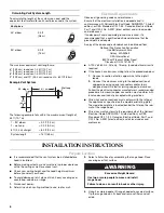
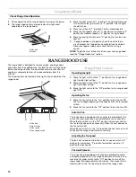
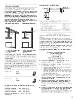
Venting Methods
A 6" (15.2 cm) round vent system is needed for installation (not
included). A dual 6" (15.2 cm) round vent system is needed for
the 48" (121.9 cm) range hood. The hood exhaust opening is 6"
(15.2 cm) round.
NOTE: Flexible vent is not recommended. Flexible vent creates
back pressure and air turbulence that greatly reduce
performance.
Vent system can terminate either through the roof or wall. To vent
through a wall, a 90° elbow is needed.
*The 48" (121.9 cm) hood uses two 6" (15.2 cm) round vents or
transitions to 10" (25.4 cm) round vent using Part Number
4396915.
See NOTE
X
36" (91.4 cm)
Countertop
height
Roof Venting
Wall Venting
A. Roof cap
B. 6" (15.2 cm) round vent
A. Wall cap
B. 6" (15.2 cm) round vent
A
A
B*
B*


