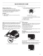
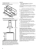
background image

7

To remove filters:

NOTE: Use 2 hands to remove the filters, one to pull and turn 
the knob, the other to hold the filter so that it doesn’t fall.

Pull knob forward (toward the front of the hood) while 
turning the knob counterclockwise to release the locking 
lever.

Slide the filter down and away from the front retaining 
channel.

5. Slide apart the chimney covers.

NOTE: To avoid damage to the chimney covers, do not 
remove the plastic coverings at this time.

The chimney section of the hood is shipped assembled. It 
must be disassembled for installation.

6. Remove the lower chimney cover from the chimney support 

by removing the two Phillips screws on the outside bottom of 
the chimney cover.

7. Remove the upper chimney cover from the chimney support 

by removing the two Phillips screws on the outside top of the 
chimney cover.

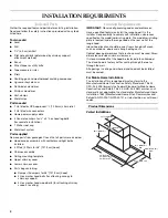
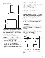
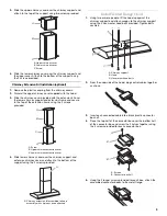
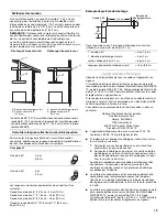
8. Determine and mark the centerline on the ceiling where the 

hood will be installed, making sure that the hood is centered 
over the cooking surface.

9. Tape the template (supplied in the chimney support carton) to 

the ceiling and mark the mounting holes, electrical hole and 
vent location on the ceiling.

10. Drill pilot holes in the chimney support mounting hole 

locations for your attachment method.

11. Use a 

1¹⁄₄

" or 3.0 cm drill bit to drill the hole for the power 

supply cable.

12. Cut the hole for the vent system in the ceiling and install the 

vent system. See “Venting Requirements” section.

13. If roof or wall does not have a damper, place the round 

damper into the exhaust opening of the vent motor housing. 
The 48" (121.9 cm) hood requires 2 dampers.

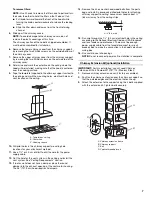
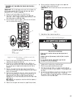
14. Remove the 4 hex washer head wood bolts from the parts 

bag and install in previously drilled pilot holes for attaching 
chimney support to ceiling. Leave screw heads about ¼" 
(6.4 mm) away from the ceiling strips. 

15. Run wire through the 1

¹⁄₄

" (3.0 cm) electrical hole in the ceiling 

according to the National Electrical Code or CSA Standards 
and local codes and ordinances. There must be enough 
power supply cable from the fused disconnect (or circuit 
breaker) box to make the connection in the hood’s electrical 
wiring box.

16. Use caulk to seal all openings.

NOTE: Do not reconnect power until installation is complete.

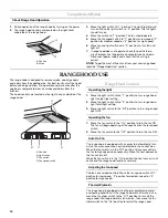
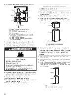
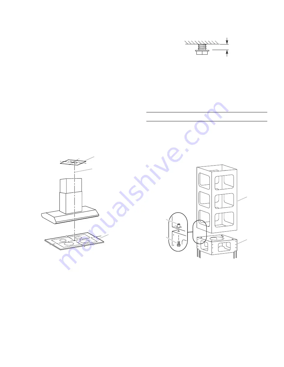
Chimney Extension Kit (optional) Installation

IMPORTANT: For this installation, you will need Chimney 
Extension Kit Part Number W10197713 (Stainless Steel).

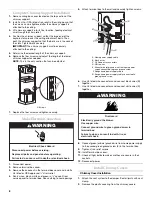
1. Remove chimney extension cover (if factory assembled).

2. Position the chimney extension over the chimney support so 

that the outside edges and the electrical holes line up.

3. Attach the extension to the support using the 4 bolts supplied 

with the extension kit. Tighten bolts securely.

A. Template on ceiling
B. Centerline

C. Cooking surface

A

B

C

A. 

¹⁄₄

" (6.4 mm)

A. Chimney extension frame
B. Chimney support

C. Bolt
D. Captive threaded insert

A

B

A

D

C

Summary of Contents for KICU460WSS0

Page 1: ...SINECONFIGURÉEENÎLOT Instructionsd installationetGuided utilisationetd entretien Au Canada pour assistance installation ou service composez le 1 800 807 6777 ou visitez notre site web à www KitchenAid ca Para obtener acceso al manual de uso y cuidado en español o para obtener información adicional acerca de su producto visite www kitchenaid com Tenga listo su número de modelo completo Puede encont...

Page 2: ...allation des cache cheminée 22 Installation de la hotte 23 Achever l installation 23 UTILISATION DE LA HOTTE DE CUISINIÈRE 24 Commandes de la hotte de cuisinière 24 ENTRETIEN DE LA HOTTE DE CUISINIÈRE 25 Lampes de la hotte de cuisinière 25 Nettoyage 25 SCHÉMA DE CÂBLAGE 26 ASSISTANCE OU SERVICE 27 Accessoires 27 GARANTIE 28 RANGE HOOD SAFETY You can be killed or seriously injured if you don t imme...

Page 3: ...ire and to properly exhaust air be sure to duct air outside do not vent exhaust air into spaces within walls or ceilings attics or into crawl spaces or garages WARNING TO REDUCE THE RISK OF FIRE USE ONLY METAL DUCTWORK WARNING TO REDUCE THE RISK OF A RANGE TOP GREASE FIRE Never leave surface units unattended at high settings Boilovers cause smoking and greasy spillovers that may ignite Heat oils s...

Page 4: ... ceiling LocationRequirements IMPORTANT Observe all governing codes and ordinances Have a qualified technician install the range hood It is the installer s responsibility to comply with installation clearances specified on the model serial rating plate The model serial rating plate is located inside the range hood on the rear wall of the range hood Island hood location should be away from strong d...

Page 5: ...ll or roof opening around the cap The size of the vent should be uniform Cold Weather Installations An additional back draft damper should be installed to minimize backward cold air flow and a thermal break should be installed to minimize conduction of outside temperatures as part of the vent system The damper should be on the cold air side of the thermal break The break should be as close as poss...

Page 6: ... copper to aluminum Follow the electrical connector manufacturer s recommended procedure Aluminum copper connection must conform with local codes and industry accepted wiring practices Wire sizes and connections must conform with the rating of the appliance as specified on the model serial rating plate The model serial plate is located behind the filter on the rear wall of the range hood Wire size...

Page 7: ...upply cable 12 Cut the hole for the vent system in the ceiling and install the vent system See Venting Requirements section 13 If roof or wall does not have a damper place the round damper into the exhaust opening of the vent motor housing The 48 121 9 cm hood requires 2 dampers 14 Remove the 4 hex washer head wood bolts from the parts bag and install in previously drilled pilot holes for attachin...

Page 8: ... to terminal box Use caulking to seal openings 5 Attach terminal box to the wall and securely tighten screws 6 Use UL listed wire connectors and connect black wires B together 7 Use UL listed wire connectors and connect white wires D together 8 Connect green or bare ground wire from home power supply to the unused green ground screw E in the terminal box 9 Tighten strain relief screws 10 Install t...

Page 9: ...crews provided InstallVentedRangeHood 1 Using two or more people lift the hood up against the chimney support and attach canopy to the chimney support using the 4 hex washer head bolts provided Tighten bolts securely 2 From the underside of the hood plug control cables together as shown 3 Insert each connected cable into a black plastic connector box half 4 Place the top half of the connector box ...

Page 10: ...he light switch to the 1 position to turn range hood light to night light setting 2 Move the light switch to the 2 position to turn range hood light to full light setting 3 Move the light switch to the Off position to turn range hood light OFF Operating the fan 1 Move the fan switch to the On position to turn the fan ON The fan will begin operating at the speed set on the fan speed switch 2 Move t...

Page 11: ... auto on switch to the O position sensor Off The switch is located behind the filters See Metal Filters in this section to remove the filters When cleaning or servicing is complete move the fan auto on switch to the I position sensor On Exterior surfaces To avoid damage to the exterior surface do not use steel wool or soap filled scouring pads Rub in direction of the grain line to avoid scratching...

Page 12: ...4 5 6 7 8 W BR GY 1 2 3 1 3 2 4 4 6 3 5 6 8 5 7 SLL BK GY W BU BK GY W BU 3 6 5 2 1 4 1 4 5 2 3 6 3 6 5 2 1 4 1 4 5 2 3 6 W BU BK BR Y GY W BU BK BR Y GY 2 4 1 3 3 4 1 2 Halogen Lamps Toroidal Transformer Y G Motor Group Motor Group Y G M Pro UL M Pro UL Motor Speed Connections To Terminals OHM Resistance Between Terminals See Connections 1 2 3 1 4 2 4 15 8 1 1 3 4 11 0 0 8 5 7 0 4 BR GY Y G 1 2 3...

Page 13: ...n the United States To locate the KitchenAid designated service company in your area you can also look in your telephone directory Yellow Pages For further assistance If you need further assistance you can write to KitchenAid with any questions or concerns at KitchenAid Brand Home Appliances Customer eXperience Center 553 Benson Road Benton Harbor MI 49022 2692 Please include a daytime phone numbe...

Page 14: ...id servicer is not available 9 The removal and reinstallation of your major appliance if it is installed in an inaccessible location or is not installed in accordance with published installation instructions 10 Major appliances with original model serial numbers that have been removed altered or cannot be easily determined This warranty is void if the factory applied serial number has been altered...

Page 15: ...as de non respect des instructions Votre sécurité et celle des autres est très importante Nous donnons de nombreux messages de sécurité importants dans ce manuel et sur votre appareil ménager Assurez vous de toujours lire tous les messages de sécurité et de vous y conformer AVERTISSEMENT DANGER Voici le symbole d alerte de sécurité Ce symbole d alerte de sécurité vous signale les dangers potentiel...

Page 16: ... à l extérieur ne pas décharger l air aspiré dans un espace vide du bâtiment comme une cavité murale un plafond un grenier un vide sanitaire ou un garage AVERTISSEMENT POUR RÉDUIRE LE RISQUE D INCENDIE UTILISER UNIQUEMENT DES CONDUITS MÉTALLIQUES AVERTISSEMENT POUR MINIMISER LE RISQUE D UN FEU DE GRAISSE SUR LA CUISINIÈRE Ne jamais laisser un élément de surface fonctionner à puissance de chauffage...

Page 17: ...ort de cheminée 4 vis à bois tête hexagonale à embase pour fixation du support de cheminée au plafond Exigencesd emplacement IMPORTANT Observer les dispositions de tous les codes et règlements en vigueur Confier l installation de la hotte à un technicien qualifié C est à l installateur qu incombe la responsabilité de respecter les distances de séparation exigées spécifiées sur la plaque signalétiq...

Page 18: ...ois coudes à 90 Veiller à ce qu il y ait une section droite de conduit de 24 61 cm ou plus entre deux coudes si on doit utiliser plus de un raccord coudé Ne pas installer 2 coudes ensemble Au niveau de chaque jointure du conduit de décharge assurer l étanchéité avec les brides de serrage pour conduit Autour de la bouche de décharge murale ou par le toit assurer l étanchéité avec un produit de calf...

Page 19: ...ueur locaux Si les codes le permettent et si on utilise un conducteur distinct de liaison à la terre il est recommandé qu un électricien qualifié vérifie la qualité de la liaison à la terre Pour obtenir un exemplaire de la norme des codes ci dessus contacter National Fire Protection Association One Batterymarch Park Quincy MA 02269 CSA International 8501 East Pleasant Valley Road Cleveland OH 4413...

Page 20: ...térieur du cache cheminée 8 Déterminer et marquer l axe central de la hotte au plafond là où la hotte sera installée en veillant à ce que la hotte soit centrée au dessus de la surface de cuisson 9 Avec du ruban adhésif fixer le gabarit fourni dans l emballage du support de cheminée au plafond et marquer la position des trous de montage du trou de passage du câble électrique et du conduit d évacuat...

Page 21: ...iveau des vis de fixation au plafond pousser ensuite le support de cheminée pour engager les vis sur la partie étroite des trous de fixation Bien serrer les vis IMPORTANT Le support de cheminée doit être solidement fixé au plafond 5 Déterminer la longueur nécessaire du support de cheminée 6 Ôter les quatre vis et ajuster la longueur du support de cheminée inférieur selon le besoin REMARQUE C est l...

Page 22: ... section supérieure du cache cheminée Fixer sur le bas du support avec deux vis fournies Installation de l ensemble d extension de cheminée option 1 Ôter la feuille de plastique de protection des sections du cache cheminée 2 Jeter la protection du cache cheminée supérieur fournie avec la hotte 3 Enfiler le cache cheminée fourni avec la section d extension sur le support de cheminée inférieur et l ...

Page 23: ...fonctionnement de la hotte 2 Les commandes sont situées sous la hotte du côté droit 3 Placer le commutateur d éclairage à la position 1 La veilleuse devrait s allumer Placer le commutateur d éclairage à la position 2 Le plein éclairage devrait s allumer 4 Pousser le commutateur du ventilateur à la position 1 Le ventilateur devrait fonctionner 5 Placer le commutateur de vitesse du ventilateur à la ...

Page 24: ...ilateur à la position Off pour éteindre le ventilateur Activation automatique du ventilateur La hotte est dotée d un capteur qui met automatiquement le ventilateur en marche lorsqu une quantité de chaleur excessive est détectée dans la zone du module de commande Lorsque le commutateur du ventilateur est à la position Off ce capteur met en marche le ventilateur à la vitesse élevée lorsque c est néc...

Page 25: ...atique activé à la position O capteur désactivé Le commutateur se trouve derrière les filtres Voir Filtres métalliques dans cette section pour retirer les filtres Une fois le nettoyage ou l entretien terminé placer le commutateur de ventilateur auto on ventilateur automatique activé à la position I capteur activé Surfaces externes Pour éviter d endommager la surface externe ne pas utiliser de tamp...

Page 26: ...S BL BU N GRIS BL BU 3 6 5 2 1 4 1 4 5 2 3 6 3 6 5 2 1 4 1 4 5 2 3 6 BL BU N MAR JA GRIS BL BU N MAR JA GRIS 2 4 1 3 3 4 1 2 JA VE M Pro UL M Pro UL 1 2 3 1 4 2 4 15 8 1 1 3 4 11 0 0 8 5 7 0 4 MAR GRIS 1 2 3 4 X1 X1 6 7 5 8 X1 10 11 9 12 X1 1 2 3 1 4 2 4 15 8 1 1 3 4 11 0 0 8 5 7 0 4 JA VE JA VE JA VE Éclairage 0 1 2 1 Ensemble du moteur Ensemble du moteur Résistance en ohms entre les bornes voir ...

Page 27: ... vous renseigneront sur les sujets suivants Caractéristiques et spécifications sur toute notre gamme d appareils électroménagers Consignes d utilisation et d entretien Vente d accessoires et de pièces de rechange Références aux marchands locaux aux distributeurs de pièces de rechange et aux compagnies de service Les techniciens de service désignés par KitchenAid Canada sont formés pour remplir la ...

Page 28: ... d installation fournies 10 Les gros appareils ménagers dont les numéros de série et de modèle originaux ont été enlevés modifiés ou qui ne peuvent pas être facilement identifiés La présente garantie est nulle si le numéro de série d usine a été modifié ou enlevé du gros appareil ménager Le coût d une réparation ou d un remplacement dans le cadre de ces circonstances exclues est à la charge du cli...

Reviews: