background image

10

Electrical Requirements - U.S.A.
Only

If codes permit and a separate ground wire is used, it is
recommended that a qualified electrical installer determine that
the ground path and wire gauge are in accordance with local
codes.

Do not use an extension cord.

Be sure that the electrical connection and wire size are adequate
and in conformance with the National Electrical Code, ANSI/
NFPA 70-latest edition and all local codes and ordinances.

A copy of the above code standards can be obtained from:

National Fire Protection Association

1 Batterymarch Park

Quincy, MA 02169-7471

WARNING:

Improper connection of the equipment-grounding

conductor can result in a risk of electric shock. Check with a
qualified electrician or service technician if you are in doubt as to
whether the appliance is properly grounded. Do not modify the
power supply cord plug. If it will not fit the outlet, have a proper
outlet installed by a qualified electrician.

Electrical Connection

To properly install your range, you must determine the type of
electrical connection you will be using and follow the instructions
provided for it here.

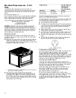
Range must be connected to the proper electrical voltage and
frequency as specified on the model/serial/rating plate. The
model/serial/rating plate is located behind the oven door on the
top right-hand side of the oven frame.

A.

Model/serial/rating plate (located behind the oven door on the top
right-hand side of the oven frame)

This range is manufactured with the neutral terminal
connected to the cabinet. Use a 3-wire, UL listed, 40 or 50 A
power supply cord (pigtail). See the following Range Rating
chart. If local codes do not permit ground through the neutral,
use a 4-wire power supply cord rated at 250 V, 40 or 50 A and
investigated for use with ranges.

Range Rating*

Specified Rating of
Power Supply
Cord Kit and
Circuit Protection

120/240 V

120/208 V

Ampere

8.8-16.5 kW

7.8-12.5 kW

40 or 50**

16.6-22.5 kW

12.6-18.5 kW

50

*The NEC calculated load is less than the total connected load
listed on the model/serial/rating plate.

**If connecting to a 50 A circuit, use a 50 A rated cord with kit. For
50 A rated cord kits, use kits that specify use with a nominal 1

3

/

8

"

(3.5 cm) diameter connection opening.

A circuit breaker is recommended.

The range can be connected directly to the circuit breaker box
(or fused disconnect) through flexible or nonmetallic sheathed,
copper or aluminum cable. See the “Electrical Connection -
U.S.A. Only” section.

Allow at least 6 ft (1.8 m) of slack in the line so that the range
can be moved if servicing is ever necessary.

A UL listed conduit connector must be provided at each end of
the power supply cable (at the range and at the junction box).

Wire sizes and connections must conform with the rating of the
range.

The tech sheet is available online, and the wiring diagram is
located on the back of the range in a plastic bag.

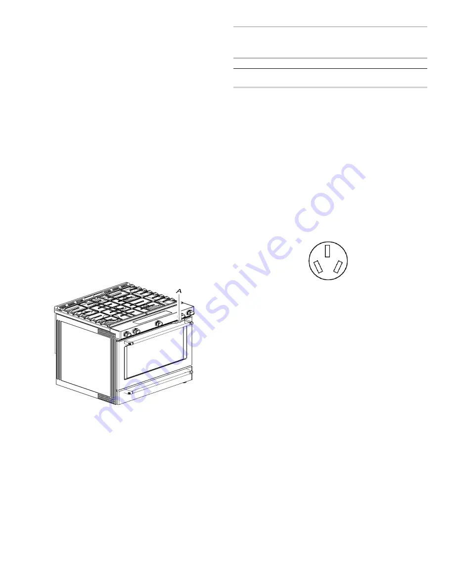
3-wire receptacle (10-50R)

If Connecting to a 3-Wire System:

Local codes may permit the use of a UL listed, 3-wire, 250 V, 40 or
50 A range power supply cord (pigtail). This cord contains 3
copper conductors with ring terminals or open-end spade
terminals with upturned ends, terminating in a NEMA Type 10-50P
plug on the supply end. Connectors on the appliance end must be
provided at the point the power supply cord enters the appliance.
This uses a 3-wire receptacle of NEMA Type 10-50R.

If Connecting to a 4-Wire System

This range is manufactured with the ground connected to the
neutral by a link. The ground must be revised so the green ground
wire of the 4-wire power supply cord is connected to the cabinet.
See “Electrical Connection - U.S.A. Only” section.

Grounding through the neutral conductor is prohibited for new
branch-circuit installations (1996 NEC); mobile homes; and
recreational vehicles, or an area where local codes prohibit
grounding through the neutral conductor.

When a 4-wire receptacle of NEMA Type 14-50R is used, a
matching UL listed, 4-wire, 250 V, 40 or 50 A, range power supply
cord (pigtail) must be used. This cord contains 4 copper
conductors with ring terminals or open-end spade terminals with
upturned ends, terminating in a NEMA Type 14-50P plug on the
supply end.

Summary of Contents for KSDB900ESS

Page 1: ...me de nettoyage 34 Nettoyage général 35 INSTRUCTIONS D INSTALLATION 36 EXIGENCE 36 Outils et pièces 36 Exigences d emplacement 37 Spécifications électriques Canada seulement 39 Spécifications de l alimentation en gaz 39 INSTALLATION 40 Déballage de la cuisinière 40 Installation de la bride antibasculement 41 Réglage des pieds de nivellement 42 Réglage de l aplomb de la cuisinière 42 Raccordement é...

Page 2: ...roperty damage personal injury or death If a fire should occur keep away from the appliance and immediately call your fire department DO NOT ATTEMPT TO EXTINGUISH AN OIL GREASE FIRE WITH WATER The range will not tip during normal use However the range can tip if you apply too much force or weight to the open door without the anti tip bracket fastened down properly WARNING Tip Over Hazard A child o...

Page 3: ...tely follow instructions WARNING You can be killed or seriously injured if you don t follow instructions All safety messages will tell you what the potential hazard is tell you how to reduce the chance of injury and tell you what can happen if the instructions are not followed IMPORTANT Do not install a ventilation system that blows air downward toward this gas cooking appliance This type of venti...

Page 4: ...ture Utensil Handles Should Be Turned Inward and Not Extend Over Adjacent Surface Units To reduce the risk of burns ignition of flammable materials and spillage due to unintentional contact with the utensil the handle of a utensil should be positioned so that it is turned inward and does not extend over adjacent surface units Disconnect power before servicing This appliance is equipped with a thre...

Page 5: ... oven Clean Only Parts Listed in Manual Before Self Cleaning the Oven Remove broiler pan and other utensils Wipe off all excessive spillage before initiating the cleaning cycle For units with ventilating hood Clean Ventilating Hoods Frequently Grease should not be allowed to accumulate on hood or filter When flaming foods under the hood turn the fan on For smart enabled ranges and ovens Remote ope...

Page 6: ...ve them with a non scratch scrubbing sponge or plastic scraper Additional Clean cycles may be run to help remove the stubborn soils IMPORTANT Do not use oven cleaners The use of chemicals including commercial oven cleaners or metal scouring pads may cause permanent damage to the porcelain surface of the oven interior NOTES The range should be level to ensure that the entire surface of the bottom o...

Page 7: ...d spills containing acids such as vinegar and tomato should be cleaned as soon as the cooktop grates and caps are cool These spills may affect the finish To avoid chipping do not bang grates and caps against each other or hard surfaces such as cast iron cookware Do not reassemble caps on burners while wet Do not clean in the Self Cleaning cycle Do not clean in dishwasher Cleaning Method Nonabrasiv...

Page 8: ...tart Guide for ordering information Side Trim Kits 5 8 1 7 cm White Order Part Number W10675027 5 8 1 7 cm Black Order Part Number W10675026 5 8 1 7 cm Stainless Steel Order Part Number W10675028 11 8 2 9 cm White Order Part Number W10731885 11 8 2 9 cm Black Order Part Number W10731886 11 8 2 9 cm Stainless Steel Order Part Number W10731887 Backsplash Kits High 6 15 2 cm White Order Part Number W...

Page 9: ...door may protrude beyond the base cabinet Slide in Cutout Freestanding Cutout A 18 45 7 cm upper side cabinet to countertop B 13 33 cm maximum upper cabinet depth C 30 76 2 cm minimum opening width D For minimum clearance to top of cooktop see NOTE E 30 76 5 cm minimum opening width F 5 12 7 cm minimum clearance from both sides of range to side wall or other combustible material G The shaded area ...

Page 10: ...ss than the total connected load listed on the model serial rating plate If connecting to a 50 A circuit use a 50 A rated cord with kit For 50 A rated cord kits use kits that specify use with a nominal 13 8 3 5 cm diameter connection opening A circuit breaker is recommended The range can be connected directly to the circuit breaker box or fused disconnect through flexible or nonmetallic sheathed c...

Page 11: ...rnational Certified Power Cord intended to be plugged into a standard 14 50R wall receptacle Be sure the wall receptacle is within reach of range s final location Do not use an extension cord The tech sheet is available online and the wiring diagram is located on the back of the range in a plastic bag Gas Supply Requirements WARNING Explosion Hazard Use a new CSA International approved gas supply ...

Page 12: ...l not applicable for Canada Gas Supply Pressure Testing Gas supply pressure for testing regulator must be at least 1 2 5 cm water column pressure above the manifold pressure shown on the model serial rating plate Line pressure testing above 1 2 psi 3 5 kPa gauge 14 35 6 cm WCP The range and its individual shutoff valve must be disconnected from the gas supply piping system during any pressure test...

Page 13: ...ds 3 Determine and mark centerline of the cutout space The mounting bracket can be installed on either the left hand or right hand side of the cutout Position mounting bracket against the wall in the cutout so that the V notch of the bracket is 121 2 31 8 cm from centerline as shown A 121 2 31 8 cm B Bracket V notch 4 Drill two 1 8 3 mm holes that correspond to the bracket holes of the determined ...

Page 14: ...ust the rear legs 4 When the range is at the correct height check that there is adequate clearance under the range for the anti tip bracket Before sliding range into its final location check that the anti tip bracket will slide under the range and onto the rear leveling leg prior to anti tip bracket installation NOTE If a Trim Kit will be used the top of the cooktop should be higher than the count...

Page 15: ...ng chassis ground conductor to neutral wire of power supply cord 1 Feed the power supply cord through the strain relief on the cord conduit plate on bottom of range Allow enough slack to easily attach the wiring to the terminal block A Terminal block B Ground link screw C UL listed strain relief D Power supply cord wires large opening 2 Use 3 8 1 0 cm nut driver to connect the neutral white wire t...

Page 16: ... strain relief D Power supply cord wires 4 Use a Phillips screwdriver to connect the green ground wire from the power supply cord to the range with the ground link screw and ground link section The ground wire must be attached over the ground link section 5 Use 3 8 1 0 cm nut driver to connect the neutral white wire to the center terminal block post with one of the 10 32 hex nuts A 10 32 hex nut B...

Page 17: ...Tighten strain relief screw against the flexible conduit Direct Wire Installation Copper or Aluminum Wire This range may be connected directly to the fuse disconnect or circuit breaker box Depending on your electrical supply make the required 3 wire or 4 wire connection 1 Strip outer covering back 3 7 6 cm to expose wires Strip the insulation back 3 8 1 0 cm from the end of each wire 2 Allow enoug...

Page 18: ...2 3 N m Wire Awg Torque 8 gauge copper 25 lbs in 2 8 N m 6 gauge aluminium 35 lbs in 4 0 N m 3 Use 3 8 1 0 cm nut driver to connect the bare green ground wire to the center terminal block post with one of the 10 32 hex nuts A 10 32 hex nut B Line 2 red wire C Ground link screw D Bare green ground wire E Line 1 black wire F Terminal lug 4 Connect line 2 red and line 1 black wires to the outer termi...

Page 19: ...ugs to the terminal block 20 lbs in 2 3 N m Wire Awg Torque 8 gauge copper 25 lbs in 2 8 N m 6 gauge aluminium 35 lbs in 4 0 N m 5 Use a hex or Phillips screwdriver to connect the bare green ground wire to the range with the ground link screw and ground link section The ground wire must be attached over the ground link section and must not contact any other terminal 6 Use 3 8 1 0 cm nut driver to ...

Page 20: ...h and an adjustable wrench to attach the flexible connector to the adapters IMPORTANT All connections must be wrench tightened Do not make connections to the gas regulator too tight Making the connections too tight may crack the regulator and cause a gas leak Do not allow the regulator to turn when tightening fittings A 1 2 1 3 cm or 3 4 1 9 cm gas pipe B Use pipe joint compound C Adapter D Manual...

Page 21: ...t of the warming drawer or baking drawer to keep the range from moving and then grasp the back of the range as shown 3 Slowly attempt to tilt the range forward If you encounter immediate resistance the range foot is engaged in the anti tip bracket Go to Step 8 4 If the rear of the range lifts more than 1 2 1 3 cm off the floor without resistance stop tilting the range and lower it gently back to t...

Page 22: ...turn the control knobs to the off position and contact your dealer or authorized service company for assistance Please reference the Warranty section of the User Guide to contact service If the cooktop low burner flame needs to be adjusted for any of the burners see the Adjust Flame Height section Power Failure In case of prolonged power failure the surface burners can be lit manually Hold a lit m...

Page 23: ... materials 5 Check that the range is level See the Level Range section 6 Use a mild solution of liquid household cleaner and warm water to remove waxy residue caused by shipping material Dry thoroughly with a soft cloth For more information see the Range Maintenance and Care section 7 Read the Quick Start Guide and online Control Guide 8 Turn on surface burners and oven See the Quick Start Guide a...

Page 24: ...loss of life The qualified service agency is responsible for the proper installation of this kit The installation is not proper and complete until the operation of the converted appliance is checked as specified in the manufacturer s instructions supplied with the kit Propane Gas Conversion WARNING Tip Over Hazard A child or adult can tip the range and be killed Install anti tip bracket to floor o...

Page 25: ...talled remove the burner grates 2 Remove the burner caps 3 Remove the burner base A Igniter electrode B Burner cap C Gas tube opening D Burner base Large Burner A Burner cap B Burner base C Gas tube opening D Choke for use with large burner Propane gas only 4 Apply masking tape to the end of a 9 32 7 mm nut driver to help hold the gas orifice spud in the nut driver while changing it Press nut driv...

Page 26: ... Make Gas Connection section for proper connection of the range to the gas supply 2 Refer to the Electronic Ignition System section for proper burner ignition and operation 3 Refer to the Adjust Flame Height section for burner flame adjustments IMPORTANT You may have to adjust the low setting for each cooktop burner Checking for proper cooktop burner flame is very important Natural gas flames do n...

Page 27: ...e spud holder D Screws 5 Remove the orifice spuds shipped in the literature package in the oven Gas orifice spuds are stamped with a number marked with 1 or 2 color dots and have a groove in the hex area Replace the Natural gas orifice spud with the correct Propane gas orifice spud A Stamped number Refer to the following chart for the correct Natural gas orifice spud placement Remove choke from la...

Page 28: ...he control knob If the Low Flame Needs to be Adjusted 1 Light 1 burner and turn to lowest setting 2 Remove the control knob Hold the knob stem with a pair of pliers Use a small flat blade screwdriver to turn the screw located in the center of the control knob stem until the flame is the proper size Turning the screw clockwise will increase the flame size and turning the screw counterclockwise will...

Page 29: ...ving range slide range onto cardboard or hardboard to avoid damaging the floor covering If removing the range is necessary for cleaning or maintenance For power supply cord connected ranges 1 Slide range forward 2 Turn manual shutoff valve to the closed position 3 Unplug the power supply cord 4 Disconnect the gas supply tubing 5 Complete cleaning or maintenance 6 Reconnect the gas supply tubing 7 ...

Page 30: ...eler immédiatement le fournisseur de gaz à partir du téléphone d un voisin Suivre ses instructions À défaut de joindre votre fournisseur de gaz appeler les pompiers L installation et l entretien doivent être effectués par un installateur qualifié une agence de service ou le fournisseur de gaz AVERTISSEMENT Ne jamais faire fonctionner la surface de cuisson de la partie supérieure de cet appareil sa...

Page 31: ...ir vers le bas qui évacuerait l air vers cet appareil de cuisson à gaz Ce type de système de ventilation peut causer des problèmes d allumage et de combustion avec cet appareil de cuisson à gaz et entraîner des blessures corporelles ou le fonctionnement non désiré de cet appareil La cuisinière ne basculera pas pendant une utilisation normale Cependant la cuisinière peut basculer si vous appliquez ...

Page 32: ...eil sans recommandation spécifique du manuel Toutes les autres tâches d entretien doivent être effectuées par un technicien qualifié Entreposage dans ou sur la appareil Les matières inflammables ne doivent pas être entreposées dans un four ou près de la surface de la table Cet appareil n est pas conçu pour servir d espace de rangement Ne pas utiliser d eau sur les feux de friture Étouffer le feu o...

Page 33: ...ents chauffants ou les surfaces intérieures tant qu ils n ont pas suffisamment refroidi Les autres surfaces de l appareil peuvent devenir suffisamment chaudes pour causer des brûlures les ouvertures de ventilation et les surfaces autour de ces ouvertures les portes du four et les hublots de portes font partie de ces surfaces Il faut faire attention de ne pas laisser le papier aluminium et la sonde...

Page 34: ...grattoir en plastique Des programmes de nettoyage supplémentaires peuvent être lancés pour aider à se débarrasser des saletés tenaces IMPORTANT Ne pas utiliser de nettoyants à four L utilisation de produits chimiques y compris les nettoyants à four qu on trouve sur le marché ou des tampons à récurer métalliques pourrait causer des dommages permanents à la surface en porcelaine qui se trouve à l in...

Page 35: ...ramme le plus intensif Les saletés cuites doivent être trempées ou frottées avant d être placées au lave vaisselle Bien que les grilles de brûleurs soient durables elles perdront progressivement de leur lustre et ou se décoloreront lorsqu on les lave au lave vaisselle Nettoyant pour grille et plateau d égouttement pour installation à gaz Pièce n 31617 non fournie Consulter le Guide de démarrage ra...

Page 36: ...èces fournies Vérifier que toutes les pièces sont présentes Ensemble de conversion au gaz propane naturel Écrous hexagonaux de 10 32 fixés au bornier 3 Cosses pour câblage direct 3 Vis n 10 x 15 8 4 1 cm pour le montage de la bride antibasculement 2 Bride antibasculement à l intérieur de la cavité du four La bride antibasculement doit être solidement fixée à la cloison arrière ou au plancher La pr...

Page 37: ...un tapis isolant ou une plaque de contreplaqué de 1 4 6 4 mm IMPORTANT Afin d éviter d endommager les placards consulter l installateur ou le fabricant des placards pour déterminer si les matériaux utilisés peuvent subir une décoloration une déstratification ou d autres dommages Ce four a été conçu conformément aux exigences des normes UL et CSA International et respecte les températures maximales...

Page 38: ...erre dans cette zone grisée H 13 1 8 33 3 cm I 7 11 16 19 5 cm J 4 13 16 12 2 cm K 3 11 16 9 4 cm plus la mesure de M L La porte du placard ou ses ch arnières ne doit pas dépasser à l intérieur de l ouverture M La profondeur restante du plan de travail ne doit pas dépasser 2 1 4 5 7 cm A 18 45 7 cm entre le placard latéral supérieur et le plan de travail B 13 33 cm de profondeur maximale du placar...

Page 39: ...sation neuve d arrivée de gaz approuvée par la CSA International Installer un robinet d arrêt Bien serrer chaque organe de connexion de la canalisation de gaz En cas de connexion au gaz propane demander à une personne qualifiée de s assurer que la pression de gaz ne dépasse pas 36 cm 14 po de la colonne d eau Par personne qualifiée on comprend le personnel autorisé de chauffage le personnel autori...

Page 40: ... 1 colonne d eau à la pression de la tubulure de distribution indiquée sur la plaque signalétique Pressurisation à une pression supérieure à 1 2 lb po2 3 5 kPa 35 5 cm 14 colonne d eau Lors de tout test de pressurisation de ce système à une pression supérieure à 1 2 lb po2 3 5 kPa on doit déconnecter la cuisinière et son robinet d arrêt individuel de la canalisation de gaz Pressurisation à une pre...

Page 41: ...oujons en métal ou en bois 3 Déterminer et marquer l axe central de l espace à découper Le montage peut être effectué du côté gauche ou droit de la découpe Positionner la bride de montage contre le mur dans l ouverture de telle sorte que l encoche en V de la bride se trouve à 121 2 31 8 cm de l axe central tel qu illustré A 121 2 31 8 cm B Encoche en V de la bride 4 Percer deux trous de 1 8 3 mm q...

Page 42: ... la cuisinière vers l arrière pour ajuster les pieds avant puis incliner la cuisinière vers l avant pour ajuster les pieds arrière 4 Lorsque la cuisinière est à la hauteur souhaitée vérifier que l espace sous la cuisinière est suffisant pour loger la bride antibasculement Avant de faire glisser la cuisinière à son emplacement final vérifier qu il sera possible de faire glisser la bride antibascule...

Page 43: ... de raccordement électrique Si le domicile comporte Point de distribution Voir la section suivante Prise à 3 conducteurs type NEMA 10 50R Un cordon d alimentation pour cuisinière homologué UL 250 V minimum de 40 A ou de 50 A Connexion à 3 conducteurs cordon d alimentation électrique Prise à 4 conducteurs type NEMA 14 50R Un cordon d alimentation pour cuisinière homologué UL 250 V minimum de 40 A o...

Page 44: ...on à la terre à l arrière de la cuisinière Conserver la vis de liaison à la terre et l extrémité de la liaison à la terre sous la vis 3 Passer le cordon d alimentation par le serre câbles de la plaque pour cordon conduit en bas de la cuisinière Laisser suffisamment de mou pour raccorder facilement le câblage au boîtier de raccordement A Bornier B Vis de liaison à la terre C Serre câbles homologati...

Page 45: ... la source de courant électrique 2 Remove the lower access cover screws located on the back of the range Pull the bottom of the cover toward you and out to remove cover from range A Mounting tabs 3 B Lower access cover C Screws 2 3 Retirer du plot central du boîtier de raccordement l étiquette plastique qui maintient trois écrous hexagonaux 10 32 OU Retirer l écrou hexagonal 10 32 de chacun des tr...

Page 46: ... direct Connexion à 3 conducteurs Raccordement par câblage direct Utiliser cette méthode uniquement si les codes locaux autorisent la connexion du conducteur de mise à la terre au conducteur du neutre de l alimentation 1 Tirer le câblage à travers le conduit sur la plaque de cordon conduit en bas de la cuisinière Laisser suffisamment de mou pour raccorder facilement le câblage au boîtier de raccor...

Page 47: ...la vis de liaison à la terre et l extrémité de la liaison à la terre sous la vis 3 Tirer les conducteurs à travers le serre câbles au pied de la cuisinière Laisser suffisamment de mou pour raccorder facilement le câblage au boîtier de raccordement A Bornier B Vis de liaison à la terre C Plaque de cordon conduit D Fil de mise à la terre nu vert E Conducteur de ligne 2 rouge F Conducteur du neutre b...

Page 48: ...personne qualifiée de s assurer que la pression de gaz ne dépasse pas 36 cm 14 po de la colonne d eau Par personne qualifiée on comprend le personnel autorisé de chauffage le personnel autorisé d une compagnie de gaz et le personnel d entretien autorisé Le non respect de ces instructions peut causer un décès une explosion ou un incendie Cette cuisinière a été configurée à l usine pour l alimentati...

Page 49: ...tion en gaz Le robinet est ouvert lorsque la poignée est parallèle au conduit d alimentation en gaz A Robinet fermé B Robinet ouvert 2 Vérifier tous les raccordements en les badigeonnant d une solution de détection des fuites non corrosive approuvée L apparition de bulles indique une fuite Réparer toute fuite éventuelle 3 Ôter les chapeaux et les bases de brûleur de la table de cuisson du sachet d...

Page 50: ...aud ou tiroir de cuisson pour immobiliser la cuisinière puis saisir l arrière de la cuisinière comme illustré 3 Tenter d incliner la cuisinière vers l avant avec précaution En cas de résistance immédiate cela signifie que le pied de la cuisinière est engagé dans la bride antibasculement Passer à l étape 8 4 Si l arrière de la cuisinière se soulève de plus de 1 2 1 3 cm du plancher sans opposer de ...

Page 51: ...ur s est déclenché ou si un fusible est grillé Vérifier que les robinets d arrêt de gaz sont en position ouverte Vérifier que les chapeaux de brûleur sont correctement placés sur la base des brûleurs Répéter le processus de mise en marche Si un brûleur ne s allume pas à ce stade tourner les boutons de commande sur la position Off arrêt et contacter le revendeur ou un dépanneur agréé Se reporter à ...

Page 52: ...llation 1 Vérifier que toutes les pièces sont maintenant installées S il reste une pièce passer en revue les différentes étapes pour découvrir laquelle aurait été oubliée 2 Vérifier la présence de tous les outils 3 Vérifier que tous les accessoires de la cuisinière sont présents en particulier les grilles du four Ces accessoires peuvent se trouver dans les matériaux d emballage de la cuisinière 4 ...

Page 53: ... décès une explosion ou un incendie AVERTISSEMENT Cet ensemble de conversion doit être installé par un organisme de service qualifié conformément aux directives du fabricant ainsi qu à tous les codes applicables et à toutes les exigences des autorités compétentes Si les directives ne sont pas suivies à la lettre un incendie une explosion ou une émission de monoxyde de carbone pourrait se produire ...

Page 54: ...r la rondelle en place A Couvercle métallique B Rondelle C Capuchon du détenteur bleu 4 Retourner le capuchon du détendeur bleu à l envers et le revisser en place dans le couvercle métallique A Position pour gaz naturel B Position pour gaz propane 5 Remettre le couvercle métallique en place en le vissant solidement Ne pas serrer excessivement Conversion des brûleurs de surface du gaz naturel au ga...

Page 55: ...ans le sachet prévu à cet effet IMPORTANT Conserver les injecteurs à orifice pour gaz naturel en cas de réinstallation ultérieure pour gaz naturel 7 Réinstaller la base du brûleur 8 Réinstaller le chapeau de brûleur 9 Répéter les étapes 1 à 7 pour les autres brûleurs 10 Réinstaller le tiroir de cuisson Voir la section Dépose et repose du tiroir Achever l installation du gaz naturel au propane 1 Po...

Page 56: ...r la rondelle en place A Couvercle métallique B Rondelle C Capuchon du détenteur bleu 4 Retourner le capuchon du détendeur bleu à l envers et le revisser en place dans le couvercle métallique A Position pour gaz propane B Position pour gaz naturel 5 Remettre le couvercle métallique en place en le vissant solidement Ne pas serrer excessivement Conversion des brûleurs de surface du gaz propane au ga...

Page 57: ...rûleur 8 Réinstaller le chapeau de brûleur 9 Répéter les étapes 1 à 7 pour les autres brûleurs 10 Réinstaller le tiroir de cuisson Voir la section Dépose et repose du tiroir Achever l installation du gaz propane au gaz naturel 1 Pour le raccordement correct de la cuisinière à l alimentation en gaz se reporter à la section Raccordement au gaz 2 Pour allumer et utiliser correctement les brûleurs voi...

Page 58: ...r chaque réglage Déplacement de la cuisinière AVERTISSEMENT Risque de basculement Une personne enfant ou adulte peut faire basculer la cuisinière et subir des blessures mortelles Fixer la bride antibasculement au plancher ou au mur conformément aux instructions d installation Faire glisser de nouveau la cuisinière de façon à ce que le pied arrière de la cuisinière se trouve dans la fente de la bri...

Reviews: