background image

TECHNICAL EDUCATION

JOB AID 4317364

KAD-9

DRAWER

DISHWASHER

Summary of Contents for KUD Series

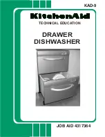
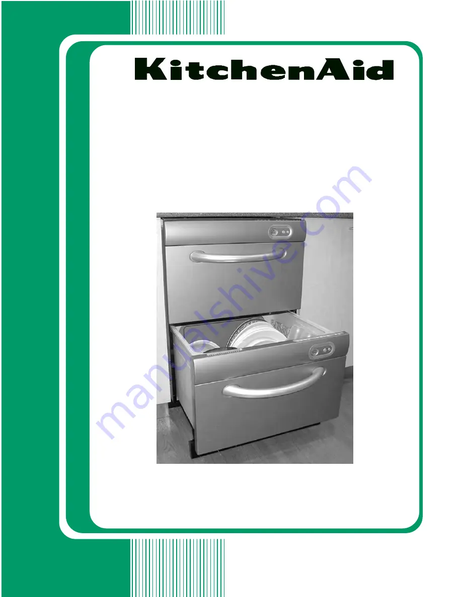
Page 1: ...TECHNICAL EDUCATION JOB AID 4317364 KAD 9 DRAWER DISHWASHER ...

Page 2: ...dishwasher The Wiring Diagram used in this Job Aid is typical and should be used for training purposes only Always use the Wiring Diagram supplied with the product when servicing the unit GOALS AND OBJECTIVES The goal of this Job Aid is to provide detailed information that will enable the service technician to properly diagnose malfunctions and repair the KitchenAid Drawer Dishwasher The objective...

Page 3: ... Removing The Spray Arm And Impeller 4 2 Removing The Isolator Badge Door Handle 4 3 Removing The Drying Fan And Rinse Aid LED 4 5 Removing The Controller 4 7 Removing The Rinse Aid And Detergent Dispenser 4 8 Removing The Upper Or Lower Drawer 4 9 Removing The Hall Sensor The Wash And Drain Motor And The Heater Element Assembly 4 10 Removing The Lid 4 13 Removing The Lid Motors 4 14 Removing The ...

Page 4: ... iv DIAGNOSTICS TROUBLESHOOTING 6 1 Diagnostics 6 1 The Error Code Display Mode 6 1 Error Codes 6 2 Diagnostic Modes 6 5 Troubleshooting Chart 6 6 WIRING DIAGRAM 7 1 Page ...

Page 5: ...kill or hurt you and others All safety messages will follow the safety alert symbol and either the word DANGER or WARNING These words mean DANGER WARNING All safety messages will tell you what the potential hazard is tell you how to reduce the chance of injury and tell you what can happen if the instructions are not followed You can be killed or seriously injured if you don t immediately follow in...

Page 6: ...OL CONSOLE F FULLY INTEGRATED I 4 INTEGRATED CONSOLE V VBL PRO LINE SERIES YEAR OF INTRODUCTION P 2004 COLOR CODE AL ALMOND ON ALMOND BL BLACK ON BLACK BT BISCUIT BS BLACK CONSOLE W STAINLESS STEEL PANELS MT METEORITE PA PANEL READY SP STAINLESS CONSOLE PANEL READY DOOR SS STAINLESS STEEL SW STAINLESS ON WHITE WH WHITE ON WHITE ENGINEERING CHANGE NUMERIC SERIAL NUMBER FP R 10 11181 MANUFACTURING S...

Page 7: ...AL NUMBER LABEL AND TECH SHEET LOCATIONS The Model Serial Number Label and Tech Sheet locations are shown below Model Serial Number Label Location On Frame Between Doors Tech Sheet Location On Inside Rear Of Cabinet ...

Page 8: ... Supply Water Flow Rate To Fill 65 gallons 2 5 liters per minute Supply Water Pressure 4 3 145 psi 30 kPa min 1000 kPa max Supply Water Temperature 120 F 48 8 C Dish Rack Nylon Dimensions Dual Dishwasher Height 32 1 4 to 34 1 4 819 4 to 869 4 mm Width 23 7 16 595 mm Depth 22 7 16 570 mm Minimum Front Panel 2 Height 28 1 4 717 5 mm Weight 124 lbs Cavity Height 32 5 16 820 mm Width 23 5 8 600 mm Dep...

Page 9: ...ot in accordance with local electrical and plumbing codes or the use of products not approved by KitchenAid or KitchenAid Canada 4 Any labor costs during the limited warranty period 5 Replacement parts or repair labor costs for units operated outside the United States or Canada 6 Pickup and delivery This product is designed to be repaired in the home 7 Repairs to parts or systems resulting from un...

Page 10: ...1 6 NOTES ...

Page 11: ...able for its size and use TOOLS AND MATERIAL REQUIRED Assemble the required tools and parts before starting installation Read and follow the in structions provided with any tools listed here utility carton knife pliers tape measure flat bladed screwdriver 2 phillips screwdriver side cutting pliers pencil sandpaper level wood cutting board adjustable wrench that opens to 1 1 8 29 mm 7 mm socket wre...

Page 12: ...be used the product depth is specified with an 11 16 18 mm door panel thickness Toekickdepth Factory supplied 2 4 3 8 5 11 cm Custom wood 5 12 7 cm less the toe kick panel thickness for integrated Minimum panel thickness using the supplied screws is 3 8 9 mm Door front height Factory supplied 30 76 2 cm Custom wood 28 1 4 71 8 cm minimum NOTE Product shown with front panels for dimension purposes ...

Page 13: ...he utility hole must be located as shown If the hole is not located as shown the hoses will prevent the dishwasher from being pushed back all the way into the cavity Make sure the edges of the utility hole are smooth or covered If the utility hole is through a metal cabinet the hole must be protected with the edge protector provided IMPORTANT Custom wood door panels if used may be wider than the d...

Page 14: ...ed electrical supply is re quired Recommended Ground Method For your personal safety this appliance must be grounded This appliance is equipped with a power supply cord having a 3 prong ground plug To minimize possible shock hazard the cord must be plugged into a mating 3 prong ground type outlet grounded in accordance with local codes and ordinances If a mating outlet is not available it is the p...

Page 15: ...ents are met 2 Prepare the cabinet opening by applying self adhesive moisture protection tape to the dry dust free underside of the counter top moisture protection tape tape 1 2 12 7 mm from front of counter top typical installation counter top Slide the brackets under the raised tabs Using the flat side of the side cutting pliers lightly tap the brackets into place Make sure the locking tabs on t...

Page 16: ...n under the at taching brackets Remove extrusion backing paper to ex pose the adhesive Carefully place the extrusion on the trim and press chassis trim edge chassis trim edge side extrusion side extrusion side extrusion open drawer top extrusion lip Finish pushing the dishwasher into the opening Proceed to Mounting The Dishwasher on page 2 10 Push the dishwasher partway into the opening As the dis...

Page 17: ...ving the drawer there is limited range of movement due to the attached water hoses DIRECT WIRING Lift the right edge of the drawer off its runner Slide the runner back into the dishwasher Lift the drawer completely off the left hand runner Rotate drawer to the right onto its side and place on the protective cover Slide the left hand runner back into the dishwasher 2 The electrical cover is located...

Page 18: ...p and replace the electrical cover 10 Pull the bottom drawer runners all the way out Make sure the latches on the back of each drawer runner are facing forward drawer runner latch latch bracket ground screw EMI filter strain relief 3 Remove factory installed power cord Disconnect the black and white wires of the electrical cord from the EMI filter Use a 7 mm socket wrench to remove the ground scre...

Page 19: ...sh against the outside edges of the drawers as shown Do not push against the middle of the drawers Push the dishwasher partway into the opening As the dishwasher is being pushed into the opening carefully pull the inlet hose and drain hose through the utility hole Allow the house wiring to gather behind the dishwasher Remove the strap from upper drawer 13 If the cabinet opening is 24 wide x 34 12 ...

Page 20: ... dishwasher to within 3 32 2 4 mm from side to side 3 32 2 4 mm minimum clearance to underside of counter 3 The dishwasher side attaching tabs are accessed through holes in the sound insu lation IMPORTANT All four attaching tabs are the recommended mounting locations Secure the attaching tabs to the cabinet using 8 phillips screws side mounting bracket Open the drawers to expose the chas sis trim ...

Page 21: ...on the runners making sure the hoses are looping upward Makesurebothrunnerclipshavesnapped into place If not pull the runner clips forward until they do Close the bottom drawer 5 Optional If the top attaching brackets are used slightly open the top drawer Screw the top attaching brackets to the undersideofthecounterwithtwo 8phillips screws The top attaching brackets can accommo date a maximum 3 4 ...

Page 22: ...hoses need to be trimmed If so trim them Slip a wire clip over each drain hose Push the hoses into the drain hose connector firmly 5 clicks Position the wire clips between the two positioning ribs on the drain hose connec tor Attach the drain hose connector to the waste tee using the supplied hose clamp Attach the drain hose support bracket to the cabinet with a 8 phillips screw at the height show...

Page 23: ... Close the drawer NOTE The drain hose connector must not support the weight of excess hose length Keep the hoses as fully extended as possible 4 3 4 12 1 cm diameter of standpipe must be large enough to create air gap valve flat seal washer inlet hose Option 1 1 1 2 3 8 cm Standpipe With Air Gap Option 2 Garbage Disposal Option 3 Air Break With Drain Hose Connector waste waste valve water supply 8...

Page 24: ...tal plate lower front panel 4 Gently feed the wires and connectors into the metal plate wire opening 5 Line up the front panel tabs to slots in metal plate Do not pull the connectorfrom wire opening metal plate slots front panel tabs 6 Push the front panel down to lock in place 7 Repeat Steps 3 through 6 for the top drawer panel 8 When installed properly top panel should be even with top of dishwa...

Page 25: ...ide on the under side of tub toe kick mounting rail clamping screw Close the drawer Check that there is 1 2 12 7 mm minimum clearance between the bottom edge of the toe kick and the floor If not remove the toe kick and shorten using the utility carton knife Remove any rough edges NOTE Rugs placed in front of dishwasher could interfere with toe kick Clearance be tween the floor and toe kick may nee...

Page 26: ...5 4 cm 5 12 7 cm 23 7 16 59 5 cm 9 22 9 cm 14 35 6 cm medallion cutout area 2 13 32 60 8 mm 1 13 64 30 6 mm Custom Front Panels Dimensions Upper and lower panel minimum thickness is 5 8 16 mm Panel thickness above 11 16 18 mm can be accommodated but product depth will increase accordingly Custom front panel material must be suitable for damp conditions or adequately sealed to withstand moisture Us...

Page 27: ...he metal plate away from the dishwasher and then pull down three inner holes centerline horizontal line top of plate front panel metal plate wire opening 8 Lay the custom front panel face down 9 Feed the medallion wires through the wire opening in the metal plate Lay the metal plate on the back of the custom front panel 10 Align the centerline marked on the custom panel with the diamond shape and ...

Page 28: ...Determine the height of the toe kick custom panel The minimum height is 2 3 4 70 5 mm Measure from the top of the adjacent cabinet door front to the floor Subtract 28 15 32 72 3 cm for needed toe kick height 4 Partially open the bottom drawer Position the custom toe kick behind the door and slide on the underside of the tub 5 Close the drawer and slide the toe kick back onto mounting rails Adjustt...

Page 29: ...ing Tempera ture is maintained by the thermistor Overheat protectionisprovidedbyathermalfuselocated on the heater plate AMOUNT OF WATER The tub fills with 0 8 gallons of water approxi mately level with the base of the spray arm Once this level is reached the wash is primed to pump water through the spray arm which will then rotate The load on the wash pump is constantly monitored throughout the wa...

Page 30: ...ll not restart if the tub is opened LID SYSTEM The lid is a single piece of injection molded polymer plastic with an integral static seal Each side of the lid is clipped into a yoke which is attached to a worm drive gearbox assembly containing a small brush type 24V DC motor At the beginning of each wash cycle both motors are powered up for approximately 10 seconds to pull the lid down onto the tu...

Page 31: ... G Model Serial Number Label left front edge between drawers H FLEXI BASKET silverware basket I Fold Down Cup Shelves J Spray Arm K Control Panel top edge of drawer L Filter Plate M Drain Filter N Powdered Detergent Dispenser inside front drawer O Rinse Aid Dispenser inside front drawer P Water Inlet inside front drawer HEA VY NO RM AL FA ST DEL IC AT E RIN SE A B C D E F G I H J K M L N O P CONTR...

Page 32: ...of water will remain in the drain filter area The filter plate is designed to be self cleaning but food scraps may accu mulate The spray arm and filter plate may need cleaning about once a month in normal use or more often should the need arise DISHWASHER SYSTEMS A Spray arm B Drain filter C Outer ring D Filter plate E Center ring F Impeller G Heater plate A B C D E F G Cleaning The Spray Arm Drai...

Page 33: ...e it from the unit Use hot soapy water and remove any soil that is present Rinse the filter plate thoroughly in clean water 4 Wipe the heater plate that is located in the drawer with a damp cloth 5 Replace the filter plate so that it lies flat in the base of the drawer 6 Align the outer ring tabs with the notches in the center ring Hold the center ring steady and turn the outer ring clockwise unti...

Page 34: ...nserpostsareareminder not to use detergent tablets A Pre Wash section B Main Wash section C Posts D Detergent dispenser latch E Rinse aid dispenser plug F Rinse aid indicator light G Water inlet opening A B C D E F G IMPORTANT Use powdered automatic dishwashing de tergent only Other detergents can produce excessive suds that can overflow out of the dishwasher and reduce washing perfor mance Add de...

Page 35: ... a water hardness test strip at no charge In the U S A call the Customer Interaction Center and ask for Part Number 4171690 See Assistance or Service in the Use and Care Guide Different brands of dishwasher detergent have different amounts of phosphorus for softening water If the water is hard and a detergent with a phosphorous content of less than 8 7 is used more detergent may be necessary or us...

Page 36: ... its highest setting 5 NOTE If there is excessive foam at the end of the wash reduce the setting If dishes are wet or streaky after drying increase the setting Filling The Dispenser The rinse aid dispenser holds 1 7 oz 50 28 mL of rinse aid Under normal conditions this will last for about 1 to 2 months Try to keep it full but do not overfill it To fill the dispenser 1 Turn the plug counterclockwis...

Page 37: ...thermometer in a glass measuring cup Tosavewater energy andtime donotrinse the dishes before placing them into the dish washer Choose the cycle that describes the most difficult soil on your dishload Do not worry about mixed loads Any item that is dishwasher safe can be washed using any cycle Use a delay feature to run your dishwasher during off peak hours Local utilities recom mend avoiding heavy...

Page 38: ... Wash Main Wash 113 F 45 C Rinse Final Rinse 122 F 50 C Dry Pre Wash Heavy Normal Quick Clean Light China Rinse Use this cycle for heavily soiled everyday dishes and hard to clean cookware Use this cycle for normally soiled dishes for optimum wash and dry performance Use this cycle for a quick wash and light dry for lightly soiled dishes Towel drying may be needed Use this cycle for lightly soiled...

Page 39: ... 2 Whenthedrainingstops openthedrawer 3 Press the desired wash program button to select the desired wash cycle The lighted indicators will progress until the desired cycle is selected 4 Check the detergent dispensers They must be filled properly for the new cycle 5 Close the drawer 6 Press START PAUSE 2 If the detergent is still visible in the deter gent dispenser you may add the item 3 Close the ...

Page 40: ...l hour delay will be programmed until the desired delay time is reached 3 Make sure the drawer is closed 4 The dishwasher will start after the set delay time has elapsed To cancel the Delay Start 1 Press the Power button or hold the Start Pause button until the indicator light turns green or blue depending on the model To enter the Option Adjustment Mode 1 Press the Power button to turn the dish w...

Page 41: ...light is orange or lavender depend ing on the model and the indicator light for the HI TEMP button is red If the indicator lightsarenoton pressthePowerbuttonto return to Normal operating mode and start again 3 Press the Lock button to turn the Auto Power feature on or off If all the red lights on the wash program panel are off the Auto Power feature has been turned off 4 Press the Power button to ...

Page 42: ...3 14 NOTES ...

Page 43: ... their locations are shown below COMPONENT LOCATIONS Rinse Aid Detergent Dispenser Pumps Wash Drain Motor Hall Sensor Heater Element Drying Fan Controller Rinse Aid LED Water Fill Valve Chassis Module Power Cord Lid Motor 1 of 4 Tub Mounted Components Cabinet Mounted Components Spray Arm Impeller Coarse Filter In Tub Components ...

Page 44: ...h or electrical shock WARNING 4 Lift the spray arm off the impeller Spray Arm Impeller 5 Rotate the outer ring on the filter plate counterclockwise CCW until the slots and tabs in the outer and inner rings align then lift the filter plate and remove it from the tub Alignment Marks Outer Ring Slot Inner Ring Tab To Remove Turn Outer Ring CCW 6 Rotate the outer ring on the impeller coun terclockwise...

Page 45: ...TE Keep the pin web in the verti cal position when you reinstall the pin in the tub 4 Pull the drawer front down so it is free of the handle and the top locating slots and remove the front Side Of Tub Pin Badge Isolator Connectors Ground Wires Isolator c Disconnect the two wire connectors from the isolator Isolator Connector Blue Wires Connector White Wires 5 To remove the isolator a Disconnect th...

Page 46: ... panel down and remove it from the door 7 To remove the badge from the door push it out of the door opening 8 To remove the door handle remove the two hex head screws Door Handle Screws Badge Inner Door Panel Slide Down Lift Pry Inner Door Panel Up ...

Page 47: ...to do so can result in death or electrical shock WARNING NOTE The drying fan and rinse aid LED are replaced as an assembly Rinse Aid LED Drying Fan 6 Pull out on the drying fan air chute and slide the chute off the drawer NOTE The top of the chute has two small slots that fit into tabs so you may have to push up on the top while you pull out to clear the tabs 7 Pull the fan LED connector off the c...

Page 48: ...id detergent dispenser pump housing unsnap the two locking tabs of the LED cover and raise the cover 10 Slide the rinse aid LED out of its holder LED Cover LED Holder Rinse Aid Detergent Dispenser Pump Housing Unsnap Tabs ...

Page 49: ...re Electrical Shock Hazard Disconnect power before servicing Replace all parts and panels before operating Failure to do so can result in death or electrical shock WARNING 5 Pull the five connectors from the edges of the controller board 6 Press in on the locking tab of the controller andremovethecontrollerfromthedrawer Controller 4 Wire FAN CONTROLLER Locking Tab 4 Wire DISPENSER 6 Wire BADGE 14 ...

Page 50: ...rinse aid and detergent dispenser Press out on the locking tab of each connector to release the connectors 9 Remove the three T10 torx screws from the left and right housing mounting brack ets and remove the brackets 10 Lower the rinse aid and detergent dispenser housing assembly into the tub and remove it Rinse Aid Detergent Dispenser 6 Remove the rinse aid LED from the rinse aid and detergent di...

Page 51: ... shown 4 Open the lower dishwasher drawer 5 Remove the door panel from the drawer see page 4 4 for the procedure 6 Press in on the tub clips on the left and right rails and push the rails back about 1 Electrical Shock Hazard Disconnect power before servicing Replace all parts and panels before operating Failure to do so can result in death or electrical shock WARNING 8 Turn the drawer over so the ...

Page 52: ... rails and remove the cover Electrical Shock Hazard Disconnect power before servicing Replace all parts and panels before operating Failure to do so can result in death or electrical shock WARNING Wiring Cover Unsnap Arm Unsnap Arm 6 Use a screwdriver and unsnap the under side of the wiring cover arms and remove the cover from the bottom of the drawer 7 Wedge a screwdriver blade into the three top...

Page 53: ...r element wiring connector 8 To remove the hall sensor a DisconnectthewireconnectoratP701 b Unclip the locking tab from the hall sensor board and lift the board up and off the motor heater housing Hall Sensor Wire Connector Locking Tab Lift Sensor e Unclipthetwolockingarmsonthemotor housing from the end of the drain hose and pull the hose out of the housing Ground Wire Heater Element Connector Dra...

Page 54: ...drain motor and the heater element from the tub 3 Motor Wire Connectors Suction Nozzle Drain Opening REASSEMBLY NOTES 1 Checkthemotorandheatersealsfor wear or damage Replace them if necessary 2 When you reinstall the heater element locking ring and wash drain motor onto thetub makesurethatthesealsbelowthe locking ring and the motor housing are properly positioned to prevent leaking 3 When tighteni...

Page 55: ...rd Disconnect power before servicing Replace all parts and panels before operating Failure to do so can result in death or electrical shock WARNING 6 Insert a regular screwdriver blade into the slot of one of the front locking arms 7 Pry down on the screwdriver far enough to fully depress the locking arm 8 Pull down on the lid so it just clears the arm NOTE Checktherubbersealsonthetopofthe lid for...

Page 56: ... operating Failure to do so can result in death or electrical shock WARNING 7 Unsnap the top arm of the lid motor from the yoke by squeezing the two tabs to gether see the photo at the top of the right column NOTE The lid will drop down at this time Support it on the drawer rail 8 Lower the lid motor and remove the wires from the motor housing clip and from the chassis module clip 9 Disconnect the...

Page 57: ...nd panels before operating Failure to do so can result in death or electrical shock WARNING Press Release Button Chassis Module Cover 7 To remove the chassis module a Remove the screw from the chassis module see the photo at the top of the right column b Unhook the locking tab from the mod ule and lift the module out of its holder c Disconnect the eight wire connectors from the module 8 To remove ...

Page 58: ... on page 4 15 for the procedure 7 Remove the water inlet line from the water fill valves then lift the valves off the hous ing and remove the valves Electrical Shock Hazard Disconnect power before servicing Replace all parts and panels before operating Failure to do so can result in death or electrical shock WARNING 8 Disconnecttheoutletlinesfromthevalves 9 Disconnectthewireconnectorlockingtabs fr...

Page 59: ...ssed into connectors far enough Resistancechecksmustbemadewithpower cord unplugged from outlet and with wiring harness or connectors disconnected DRYING FAN Refer to page 4 5 for the procedure for servic ing the drying fan 1 Unplug dishwasher or disconnect power 2 Disconnect the wire connector from the FAN terminals on the controller 3 Set the ohmmeter to the R x 1 scale 4 Touchtheohmmetertestlead...

Page 60: ... The meter should indicate between 65 and 75 Ω WASH DRAIN MOTOR Refer to page 4 10 for the procedure for servic ing the wash drain motor 1 Unplug dishwasher or disconnect power 2 Disconnect the wire connector from the MOTOR terminals on the controller 3 Set the ohmmeter to the R x 1 scale 4 Touch the ohmmeter test leads to the following terminals The meter should in dicate between 7 5 and 8 5 Ω pe...

Page 61: ...est leads to heater terminals 6 and 9 The meter should indicate between 23 and 29 Ω LID MOTOR Refer to page 4 14 for the procedure for servic ing the lid motors 1 Unplug dishwasher or disconnect power 2 Disconnect the lid motor connector from the chassis module at the appropriate following connectors P406 Upper Left P404 Upper Right P403 Lower Left P405 Lower Right 3 Set the ohmmeter to the R x 1 ...

Page 62: ...Ω 68 F 20 C 1000 Ω 86 F 30 C 1200 Ω 140 F 60 C 1 2 WATER FILL VALVES Refer to page 4 16 for the procedure for servic ing the water fill valves 1 Unplug dishwasher or disconnect power 2 Disconnect the wire connectors from the water fill valve solenoid terminals 3 Set the ohmmeter to the R x 1 scale 4 Touch the ohmmeter test leads to the up per and lower water fill valve solenoid terminals The meter...

Page 63: ...d then the Start Pause button Hold both buttons for 5 seconds The Start Pause LED is on 3 Press Start Pause The current error code is displayed on the drawer control panel LEDs followed by the previous error code 4 Press the Keylock button to clear the cur rent error code Press Keylock again to clear the previous error code 5 Press the Power button to exit the Error Code Display mode ...

Page 64: ...lace if necessary Faulty Chassis PCB 1 Unplug dishwasher or disconnect power 2 Check connections on chassis PCB re place if necessary WILL NOT RUN ON POWER UP NO LED DISPLAY MOTOR FAILURE Motor Jammed Free jammed rotor check for damage to rotor and rotor housing Stator Wiring Damaged 1 Unplug dishwasher or disconnect power 2 Check stator winding resistances replace stator if necessary Hall Sensor ...

Page 65: ...ectly 1 Unplug dishwasher or disconnect power 2 Remove lid and repair or replace lid or motor assembly Water Valve Leaking 1 Unplug dishwasher or disconnect power 2 Tighten connections or replace valve as necessary Spray Arm Is Split Replace spray arm Spray Arm Not Turning Freely Clear any obstructions to spray arm Split Inlet Hose Replace inlet hose Split Drain Hose Replace drain hose Blocked Dra...

Page 66: ...ply Valve Turned Off Turn on water supply valve Inlet Valve Failed 1 Unplug dishwasher or disconnect power 2 Check resistance of inlet valve coil replace if necessary Low Water Pressure Water pressure must be above 4 3 psi Spray Arm Not In Place Put spray arm back in proper location Obstructed Inlet Hose Or Inlet Valve Clear obstructions Bad Wiring Or Connections 1 Unplug dishwasher or disconnect ...

Page 67: ...ds to 4 Tub Home Sensor Test During the Hardware Output test mode the Keylock LED indicates the tub position Keylock LED on Tub closed Keylock LED off Tub open Fast Test Cycle The Fast Test Cycle takes approximately 7 minutes to run 1 PressthePowerbuttonforPowerOffmode Both medallion LEDs are off 2 Press the Keylock button and then the Start Pause button Hold both buttons for 5 seconds The Start P...

Page 68: ...ECTLY LOADED Advise customer of correct loading WRONG WASH CYCLE SELECTION Advise customer about lower water temperatures in Normal and Quick Clean cycles Use High Temp option Coffee tea stains left in cups NOT ENOUGH DETERGENT BEING USED Fill detergent cup to the top also fill prewash cup Run on Normal or Heavy cycle with High Temp option UPPER RACKS OVERLOADED Water cannot reach upper racks Advi...

Page 69: ...Fan Rinse Aid LED Badge Dispenser Fan Motor Wash Drain Motor Fill Valve Lid Motors Flood Chassis PCB Temperature Sensor Power Supply Resistor Heater Element Thermal Fuse Heater Plate Heater Element Relay Chassis Harness Electronic Controller M M 6 Bottom Lid 3 2 2 EMI Filter N L1 GND Top Lid Hall Sensor 3 ...

Page 70: ...7 2 NOTES ...

Page 71: ...RIZED SERVICER FOR LITERATURE ORDERS PHONE 1 800 851 4605 FOR TECHNICAL INFORMATION AND SERVICE POINTERS www servicematters com IN CANADA FOR PRODUCT SPECIFICATIONS AND WARRANTY INFORMATION CALL 1 800 461 5681 FOR TECHNICAL ASSISTANCE WHILE AT THE CUSTOMER S HOME CALL THE TECHNICAL ASSISTANCE LINE 1 800 488 4791 HAVE YOUR STORE NUMBER READY TO IDENTIFY YOU AS AN AUTHORIZED SERVICER FOR WHIRLPOOL P...

Page 72: ......

Reviews: