background image

5

8.

Install the water supply tube clamp around the water supply 
line to reduce strain on the coupling.

9.

Turn shutoff valve ON.

10.

Check for leaks. Tighten any connections (including 
connections at the valve) or nuts that leak.

Drain Pump Installation

(on some models)

NOTES:


Connect drain pump to your drain in accordance with all state 
and local codes and ordinances. 

It may be desirable to insulate drain tube thoroughly up to 
drain inlet to minimize condensation on the drain tube. 
Insulated tube kit Part Number W10365792 is available for 
purchase. 

Drain pump is designed to pump water to a maximum height 
of 10 ft (3 m). Use only Whirlpool approved drain pump kit 
Part Number 1901A. 

Do not connect the outlet end of the drain tube to a closed 
pipe system to keep drain water from backing up into the ice 
maker.

Kit Contains:

Drain pump kit Part Number 1901A

⁵⁄₈

" I.D. x 5

¹⁄₈

" drain tube (ice maker bin to drain pump 

reservoir inlet)

¹⁄₂

" I.D. x 10 ft (3 m) drain tube hose (drain pump discharge to 

household drain)

⁵⁄₁₆

" I.D. x 32" (81 cm) vent tube (drain pump reservoir vent to 

ice maker cabinet back)

Cable clamps (secures vent tube to back of ice maker) (3)

#8-32 x 

³⁄₈

" pump mounting screws (secures drain pump to 

baseplate and clamps to back of ice maker) (5)

⁵⁄₈

" small adjustable hose clamp (secures vent to drain pump)

⁷⁄₈

" large adjustable hose clamp, (secures drain tube to ice 

maker bin and drain pump reservoir inlet) (3)

Rear panel (2)

Instruction sheet

If Ice Maker Is Currently Installed

NOTE: 

If ice maker is not installed, please proceed to “Drain 

Pump Installation” section.

1.

Push the selector switch to the OFF position.

2.

Unplug ice maker or disconnect power.

3.

Turn off water supply. Wait 5 to 10 minutes for the ice to fall 
into the storage bin. Remove all ice from bin.

4.

Unscrew the drain cap from the bottom of the water pan 
located inside the storage bin. Allow water to drain 
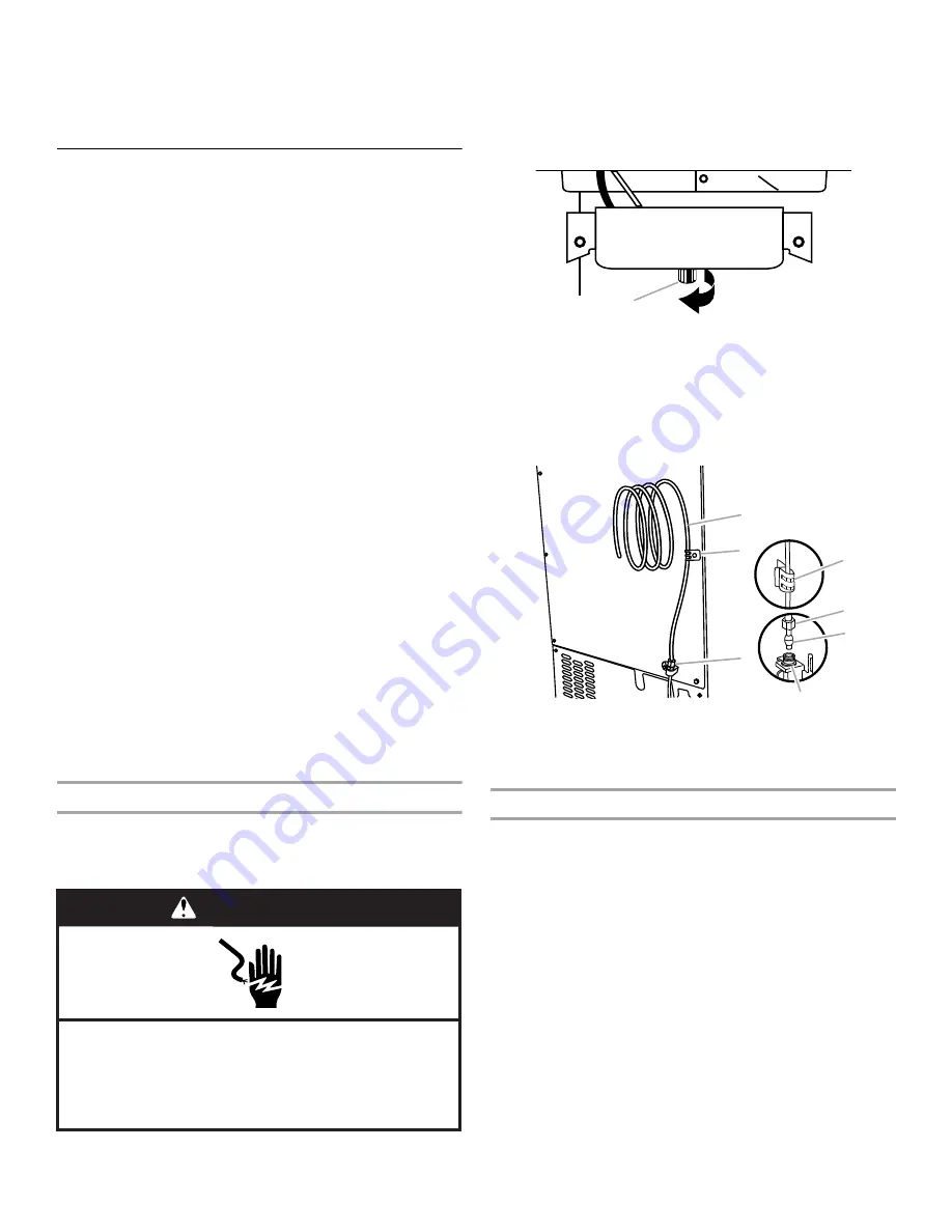
completely. Replace drain cap. See “Drain Cap” illustration.

Drain Cap

5.

If ice maker is built into cabinets, pull ice maker out of the 
opening.

6.

Disconnect water supply line. See “Water Supply Line” 
illustration.

Water Supply Line

Drain Pump Installation

NOTE: 

Do not kink, smash or damage tubes or wires during 

installation.

1.

Unplug ice maker or disconnect power.

2.

Remove rear panel. See “Rear Panel” illustration for 5 screw 
locations. Pull rear panel away from the drain tube and 
discard.

WARNING

Electrical Shock Hazard

Disconnect power before servicing.

Replace all parts and panels before operating.

Failure to do so can result in death or electrical shock.

A. Drain cap

A.

¹⁄₄

" copper tubing

B. Cable clamp

C.

¹⁄₄

" compression nut 

D. Ferrule (sleeve)

E. Ice maker connection

A

B

C

D

E

A

C

B

Summary of Contents for KUID308ESS

Page 1: ...tallation de la pompe de vidange 16 Raccordement au conduit vidange 19 Inversion du sens d installation de la porte Porte à ouverture latérale uniquement 20 Nivellement 22 Nettoyage 23 W10761663A You can be killed or seriously injured if you don t immediately You can be killed or seriously injured if you don t follow All safety messages will tell you what the potential hazard is tell you how to re...

Page 2: ...ve 55 F 13 C and below 110 F 43 C Best results are obtained between 70 F and 90 F 21ºC and 32 C The ice maker must be installed in an area sheltered from the elements such as wind rain water spray or drip When installing the ice maker under a counter follow the recommended opening dimensions shown Place electrical and plumbing fixtures in the recommended location as shown NOTES Check that the powe...

Page 3: ...you have questions about your water pressure call a licensed qualified plumber Reverse Osmosis Water Supply IMPORTANT A reverse osmosis water filtration system is not recommended for ice makers that have a drain pump installed For gravity drain systems only The pressure of the water supply coming out of a reverse osmosis system going to the water inlet valve of the ice maker needs to be between 30...

Page 4: ...sleeve and compression nut on copper tubing as shown Insert end of tubing into outlet end squarely as far as it will go Screw compression nut onto outlet end with adjustable wrench Do not overtighten 4 Place the free end of the tubing into a container or sink and turn on main water supply and flush out tubing until water is clear Turn off shutoff valve on the water pipe IMPORTANT Always drain the ...

Page 5: ...ack of ice maker 5 small adjustable hose clamp secures vent to drain pump large adjustable hose clamp secures drain tube to ice maker bin and drain pump reservoir inlet 3 Rear panel 2 Instruction sheet If Ice Maker Is Currently Installed NOTE If ice maker is not installed please proceed to Drain Pump Installation section 1 Push the selector switch to the OFF position 2 Unplug ice maker or disconne...

Page 6: ...ker power cord which is mounted to the unit base See Parts Locations illustration NOTE Clamp and screw will be reused 7 Slide drain pump into the ice maker base on the right side The pump mounting tab should slip into the rectangular slot in the ice maker base It will be necessary to tip the pump slightly to slip into the slot See Drain Pump Mounting Tab Slot illustration Drain Pump Mounting Tab S...

Page 7: ...aker as specified by the product installation instructions 17 Check all connections for leaks 18 Plug in ice maker or reconnect power 19 Turn on ice maker 20 Wait for rinsing cycle approximately 5 minutes to be sure the ice maker is operating properly Drain Connection Gravity Drain System Connect the ice maker drain to your drain in accordance with all state and local codes and ordinances If the i...

Page 8: ...ty drain system push the ice maker into position so that the ice maker drain tube is positioned over the PVC drain reducer See Gravity Drain System Style 2 For drain pump system connect the drain pump outlet hose to the drain See Drain Pump System 3 Recheck the ice maker to be sure that it is level See Leveling 4 If it is required by your local sanitation code seal the cabinet to the floor with an...

Page 9: ...at corner A Remove the screw and end cap at corner C Place the door stop at corner C and tighten screw Place the end cap at corner A and tighten screw 6 Remove the screw and door stop at corner D Remove the screw and end cap at corner B Place the door stop at corner B and tighten screw Place the end cap at corner D and tighten screw 7 Depending on your model the brand badge for the front door of y...

Page 10: ... pin Replace Door 1 Place the door on the bottom hinge pin 2 Align the door with the top hinge hole and replace the top hinge pin 3 Replace the handle and handle screws Replace Door Wrap on some models 1 Place the door wrap flange onto the door top and ensure that it fits correctly 2 Rotate the door wrap downward until it covers the door surface completely 3 Install the two hex head screws into th...

Page 11: ...to add stability when needed 5 Push up on the top rear of the ice maker and locate the leveling legs that are on the bottom rear of the ice maker 6 Follow the instructions in Step 4 to change the height of the legs 7 Use the level to recheck the ice maker to see that it is even from front to back and side to side If the ice maker is not level repeat steps 2 to 5 If the ice maker is level go to the...

Page 12: ...detergent and warm water Rinse in clean water Then clean the same parts with a solution of 1 tbs 15 mL of household bleach in 1 gal 3 8 L warm water Rinse again thoroughly in clean water NOTE Do not remove hoses Do not wash plastic parts in dishwasher They cannot withstand temperatures above 145 F 63 C 12 To replace the water pan set the water pan inside the ice bin Hook up the water pan pump Snap...

Page 13: ...mot DANGER ou AVERTISSEMENT Ces mots signifient IMPORTANTES INSTRUCTIONS DE SÉCURITÉ AVERTISSEMENT Pour réduire le risque d incendie de choc électrique ou de blessures lors de l utilisation de la machine à glaçons il convient d observer certaines précautions élémentaires CONSERVEZ CES INSTRUCTIONS Brancher sur une prise à 3 alvéoles reliée à la terre Ne pas enlever la broche de liaison à la terre ...

Page 14: ...t Choisir un endroit bien aéré où la température est supérieure à 55 F 13 C et inférieure à 110 F 43 C Pour tirer le meilleur rendement de la machine à glaçons la température ambiante doit se situer entre 70 F et 90 F 21 ºC et 32 C La machine à glaçons doit être installée à un endroit protégé contre les éléments comme le vent la pluie les embruns ou les égouttures Lorsque la machine à glaçons est ...

Page 15: ...827 kPa Si un système de filtration de l eau par osmose inverse est raccordé à votre approvisionnement en eau froide la pression de l eau au système d osmose inverse doit être de 40 à 60 lb po2 276 à 414 kPa minimum REMARQUE Le système par osmose inverse doit fournir 1 gal 3 8 L d eau par heure à la machine à glaçons pour un fonctionnement approprié de la machine à glaçons Si l on souhaite un syst...

Page 16: ... un serpentin de tube en cuivre pour permettre de sortir la machine à glaçons du placard ou du mur en cas d intervention de service Vue arrière 6 Retirer et jeter le tube court noir en plastique de l extrémité du tuyau d admission d eau 7 Visser l écrou sur l extrémité du tuyau Serrer l écrou manuellement Ensuite le serrer deux tours de plus avec une clé Ne pas serrer à l excès REMARQUE Pour évite...

Page 17: ...le mettre en position d arrêt 2 Débrancher la machine à glaçons ou déconnecter la source de courant électrique 3 Fermer l alimentation en eau Attendre 5 à 10 minutes que la glace tombe dans le bac d entreposage Enlever tous les glaçons du bac 4 Dévisser le bouchon de vidange du dessous du bac à eau situé à l intérieur du bac d entreposage Laisser l eau s évacuer complètement Réinstaller le bouchon...

Page 18: ...vis n 8 32 x fournies Voir l illustration Position des pièces 9 Raccorder le tube de vidange à la sortie de de diamètre interne du bac de la machine à glaçons à l aide de la bride de fournie Voir l illustration Tube de vidange 10 Enrouler le cordon d alimentation de la machine à glaçons de façon à former un rouleau de 4 10 2 cm de diamètre Enrouler du ruban isolant autour du cordon d alimentation ...

Page 19: ...plancher et ne cause des dommages Les tuyaux de vidange doivent avoir au moins 15 88 mm de diamètre intérieur Les tuyaux de vidange doivent avoir une pente de 1 pour chaque 48 2 54 cm pour chaque 122 cm de longueur ou une pente de pour chaque 12 6 35 mm pour chaque 30 48 cm et ne comporter aucun point bas où l eau pourrait stagner Les drains de vidange de plancher doivent être suffisamment grands ...

Page 20: ...e à la terre 2 Style 1 Pour un système de vidange par gravité pousser la machine à glaçons en position pour que le conduit de vidange soit positionné au dessus du réducteur de vidange en PVC Voir Vidange par gravité Style 2 Pour le système avec pompe de vidange connecter le tuyau de sortie de la pompe au drain Voir Système avec pompe de vidange 3 Vérifier à nouveau la machine à glaçons pour s assu...

Page 21: ...e montage des charnières 1 Dévisser et ôter la charnière supérieure Réinstaller les vis dans les trous vides de la charnière 2 Ôter les vis du côté opposé inférieur de la caisse de la machine à glaçons Inverser la charnière supérieure de telle sorte que l axe pointe vers le haut Placer la charnière du côté opposé inférieur de la machine à glaçons et serrer les vis 3 Ôter l ancienne charnière infér...

Page 22: ...déplacer la machine à glaçons le plus près possible de son emplacement final 2 Placer le niveau sur le dessus du produit pour voir si la machine à glaçons est d aplomb d avant en arrière et transversalement 3 Pousser vers le haut sur la partie supérieure avant de la machine à glaçons pour repérer les vis de nivellement qui se trouvent sur la partie inférieure avant de la machine à glaçons 4 Au moy...

Page 23: ...ur de niveau de glaçons du côté droit de la grille de coupe Tirer le détecteur de niveau vers le bas et vers l avant pour l éloigner de la grille de coupe 7 Retirer les vis de droite et de gauche Soulever la grille de coupe et la sortir REMARQUE Il faut s assurer que la cale d espacement en plastique du côté droit du support de la grille de coupe suit cette dernière 8 Retirer la vis de montage qui...

Page 24: ... intérieur du bac à glaçons Raccorder la pompe de vidange du bac à eau Remboîter le support de pompe sur le bac à eau et le remettre en place Fixer le bac à eau en réinstallant la vis de montage 13 Faire les vérifications suivantes Le bouchon de vidange du bac à eau est solidement en place Si le bouchon de vidange est desserré l eau s écoulera du bac à eau et la glace sera mince ou il n y aura pas...

Reviews: