13
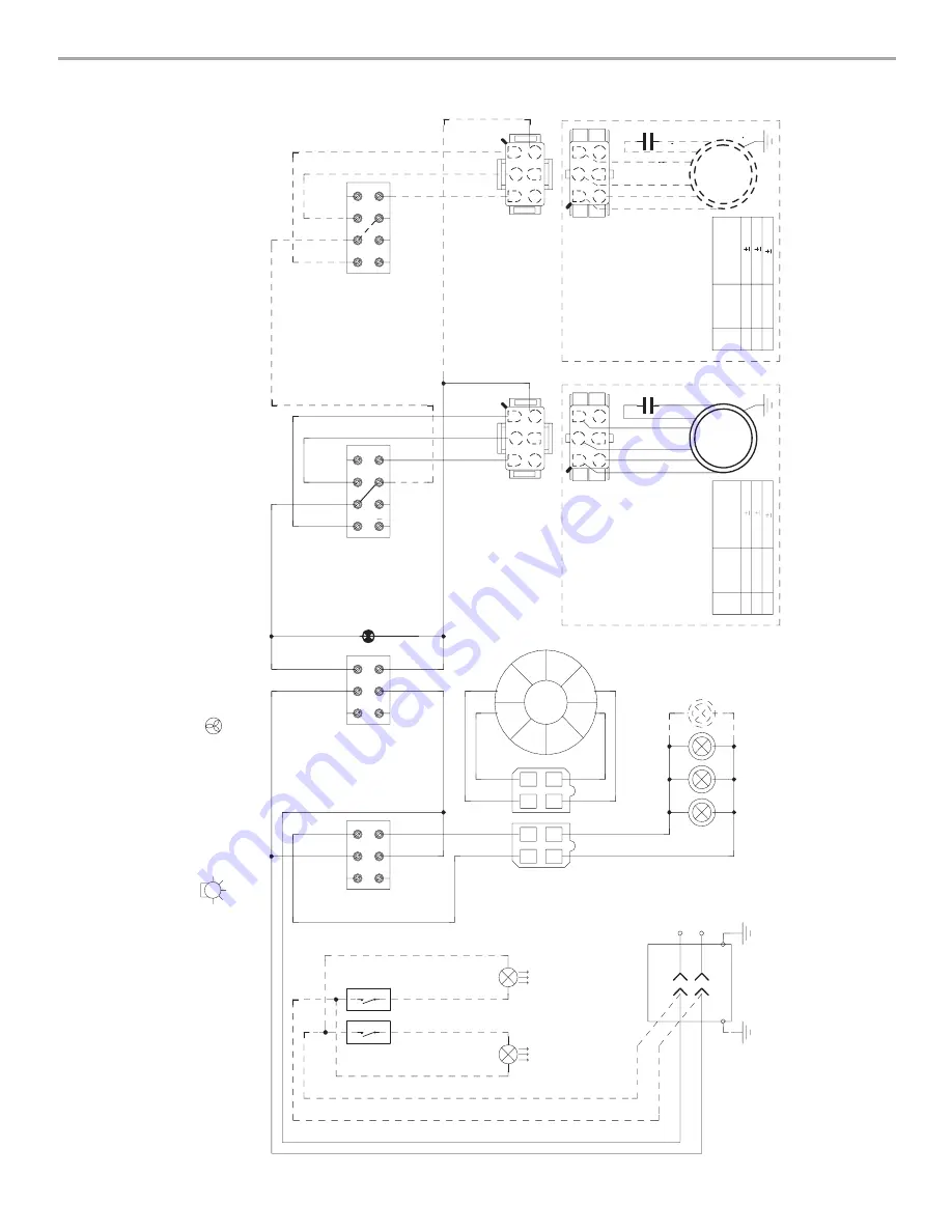
WIRING DIAGRAM
Y
BR
BK
GY
BU
W
M~
Pro UL
Y-
G
Motor
Group
BU
W
GY
BK
BK
GY
BR
W
SLS2
1 2 3 Speed
3
2
1
4
5
6
1
4
5
2
3
6
1 2 3 Speed
GY
BR
W
SLS1
2
1
4
3
5
6
7
8
2
1
4
3
5
6
7
8
BK
BR
BU
W
GY
BK
3
2
1
4
5
6
1
4
5
2
3
6
Y
BR
BK
GY
BU
W
M~
Pro UL
Y-
G
Motor
Group
0 1 M
OT
SLM
2
1
4
3
5
6
BR
BU
LP
W
BK
Toroida
l
Tr
ansf
orm
er
Halogen
Lamps
R
W
R
R
BK
BK
V
V
2
4
3
1
4
3
2
1
R
W
W
V
BK
SLL
2
1
4
3
5
6
0 1 Light
BU
R
BU
R
W
BK
BK
W
Y-
G
Y-
G
IR
Lamps
IR
Lamps
Wir
ing Bo
x
W
W
BK
BK
N
L
Line In
120
V
ac
60Hz~
Motor
Speed
Connections
To
Ter
minals
OHM Resistance
Betw
een
Te
rm
inals
(See Connections)
3
2
1
1-4 2-4 3-4
15.8 1.1 11.0 0.8 5.7 0.4
Motor
Speed
Connections
To
Ter
minals
OHM Resistance
Betw
een
Te
rm
inals
(See Connections)
3
2
1
1-4 2-4 3-4
15.8 1.1 11.0 0.8 5.7 0.4


