—
19
—
Assembly procedures
Remarks
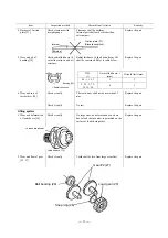
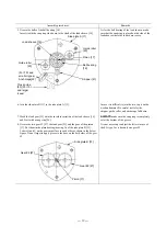
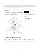
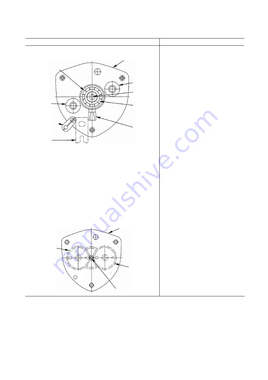
5. Grease the balls of the ball bearing [16].
Insert it with the snap ring side down to the shaft of the load sheave [14].
As for the ball bearing of the load sheave, make
sure that the snap ring is placed on the side of the
load sheave where the load chain reeves.
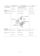
6. Join the side plate B [13] to the side plate A [11].
In case it is difficult to join the two, tap it with a
wooden hammer. Be careful not to let the
stripper, guide roller, and anchorage fall down.
7. Mesh the load gear [25] with the involute serration of the load sheave [14]
and fix it with a snap ring [26].
ALWAYS
make sure the snap ring is completely
set at the bottom of the groove.
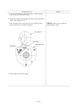
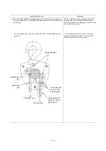
8. Grease the two gear #2 [27], the load gear [25] and the gear of the pinion
[17]. Put them in the plain bearing (bearing A) of the side plate B [13].
Letters O and V on the gears must face to each other as shown in the below
figure. Do not forget to apply grease to the boss on the both sides of the gear
#2.
It is not necessary to adjust the letters in case of
the 0.5t type, for it has only one gear #2.
Side plate A [11]
Guide roller
[20]
Pinion [17]
Ball bearing
[16]
Stripper [21]
Guide roller
[20]
Cross guide
[53] (For 10t
and larger
types)
(For 7.5t and
smaller types)
Anchorage[22]
Load sheave [14]
Side plate B [13]
Pinion [17]
Gear #2 [27]
Gear #2 [27]

