background image


Owner’s Manual 

LUBRICANT FREE 

AIR POWERED  

CHAIN HOIST        

TCL SERIES 


¼, tonne through 1 tonne Capacity 


WARNING 


Code, Lot and Serial Number 

This  equipment  should  not  be  installed,  operated  or 
maintained by any person who has not read and understood 
all  the  contents  of  this  manual.    Failure  to  read  and  comply 
with  the  contents  of  this  manual  can  result  in serious  bodily 
injury or death, and/or property damage. 

EFFECTIVE:  April 1, 2020 

Summary of Contents for TCL Series

Page 1: ...ot and Serial Number This equipment should not be installed operated or maintained by any person who has not read and understood all the contents of this manual Failure to read and comply with the contents of this manual can result in serious bodily injury or death and or property damage EFFECTIVE April 1 2020 ...

Page 2: ...ity And Regulation 3 3 Lubrication 3 4 Air Filtration 3 5 Air Dryer 3 6 Piping Hoses And Fittings 3 7 Exhaust Control 3 8 Mounting Location 3 9 Connecting Hoist to Air Supply 3 10 Mounting the Hoist 3 11 Optional Chain Container 3 12 Non Stationary Application 3 13 Preoperational Checks and Trial Operation 4 0 Operation 24 4 1 Introduction 4 2 Shall s and Shall Not s for Operation 4 3 Hoist Contro...

Page 3: ...pection Records 5 8 Inspection Methods and Criteria 6 0 Lubrication 38 6 1 Air Hoist Lubrication 6 2 Load Chain Lubrication 6 3 Hooks and Suspension Components 7 0 Maintenance Handling 40 7 1 Brake 7 2 Load Chain 7 3 Pendant 7 4 Pull Cord 7 5 Load Sheave Inspection 7 6 Storage 7 7 Outdoor Installation 7 8 Operational Environment 8 0 Troubleshooting 48 9 0 Warranty 50 10 0 Parts Information 51 ...

Page 4: ...tion operation or maintenance information which is important but not directly hazard related NOTICE These general instructions deal with the normal installation operation and maintenance situations encountered with the equipment described herein The instructions should not be interpreted to anticipate every possible contingency or to anticipate the final system crane or configuration that uses thi...

Page 5: ...able crane design and safety standards The crane designer crane manufacturer or user is responsible to furnish these additional items for compliance Refer to ANSI ASME B30 17 Safety Standard for Top Running Single Girder Cranes ANSI ASME B30 2 Safety Standard for Top Running Double Girder Cranes and ANSI ASME B30 11 Safety Standard for Underhung Cranes and Monorails If a below the hook lifting dev...

Page 6: ...responsibility of the owner user to comply with the applicable ANSI ASME B30 volume that addresses that type of equipment It is the responsibility of the owner user to have all personnel that will install inspect test maintain and operate a hoist read the contents of this manual and applicable portions of ANSI ASME B30 16 Safety Standard for Overhead Hoists and OHS Regulations If the hoist is inst...

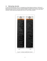
Page 7: ...ist for pendant control the warning tag is attached to the pendant hose for the pull cord control the warning tag is attached to the up cord order a tag from your dealer and install it See parts list in the parts section of this manual Read and obey all warnings attached to this hoist Tag is not shown actual size front back Figure 1 1 Warning Tag Attached to Air Hoist ...

Page 8: ...Humidity 85 or less Noise Level 83 dba maximum 1 meter when lifting rated load 93 dba maximum 1 meter when lowering rated load Supply Air 60 to 90 psi 0 4 to 0 6 MPa Air Consumption 60 to 75 cfm 1 7 to 2 1 m min Air Filtration Requirements Maximum 5 micron air filter or finer Air Lubrication Requirements Minimum 10 to 15 drops per minute 0 2 0 3 cc min of oil ...

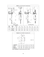
Page 9: ...itional One foot of Lift lbs No Load w Full Load No Load w Full Load Pendant Model 1 4 TCL250P 10 8 1 151 105 85 144 64 57 57 64 6 3 x 1 46 0 6 1 2 TCL500P 10 8 1 79 53 43 79 64 57 57 64 6 3 x 1 46 0 6 1 TCL1000P2 10 8 1 39 26 21 39 64 57 57 64 6 3 x 2 60 1 2 Cord Model 1 4 TCL250C 10 8 1 151 105 85 144 64 57 57 64 6 3 x 1 44 0 6 1 2 TCL500C 10 8 1 79 52 43 79 64 57 57 64 6 3 x 1 44 0 6 1 TCL1000C...

Page 10: ...s Single Fall Hoist Double Fall Hoist Cap tonne Product Code Headroom C in a in b in d in e in g in h in i in j in 1 4 TCL250P 16 3 14 4 6 6 6 4 8 0 1 0 4 4 2 2 1 0 1 2 TCL500P 16 3 14 4 6 6 6 4 8 0 1 0 4 4 2 2 1 0 1 TCL1000P2 18 0 14 4 9 0 6 4 8 0 1 1 6 3 2 7 1 9 ...

Page 11: ...4 8 0 1 0 5 3 3 3 1 0 1 2 TCL500C 16 3 14 4 8 7 6 4 8 0 1 0 5 3 3 3 1 0 1 TCL1000C2 18 0 14 4 9 0 6 4 8 0 1 1 6 3 2 7 1 9 Table 2 4 Top and Bottom Hook Dimension Units inch Product Code a b c d e f g h TCL250C P 0 6 0 8 0 6 0 8 1 4 1 3 1 0 2 9 TCL500C P 0 6 0 8 0 6 0 8 1 4 1 3 1 0 2 9 TCL1000C2 P2 1 4 0 9 1 1 0 9 1 6 1 6 1 1 4 2 Refer to Section 5 7 for inspection dimensions and limits ...

Page 12: ...12 2 3 Part Names Figure 2 1 Hoist Part Identification Diagrams TCL250C P and TCL500C P Figure 2 2 Hoist Part Identification Diagrams TCL1000C2 P2 ...

Page 13: ...Capacity of compressor s and tank Other air consuming equipment Flow restrictions such as pipes hoses valves and fittings Inadequate capacity will cause a significant drop in pressure when the hoist is operated and could cause poor performance or failure to operate 3 2 2 Regulation The hoist requires a constant supply of air at a pressure of between 60 and 90 psi If the air supply is not regulated...

Page 14: ...oy an air dryer in the air supply system to ensure that dry air is supplied to the hoist If there is moisture in the air supplied to the hoist this moisture will cause corrosion on internal hoist components during periods when the hoist is idle leading to hoist malfunction 3 6 Piping Hoses And Fittings 3 6 1 CAUTION System Configuration The system should be configured as shown in Figure 3 1 Since ...

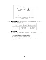
Page 15: ...CL1000C2 P2 Inside diameter 3 4 or larger Inside diameter 1 2 or larger 3 6 3 NOTICE Hoses The connection from the air supply system piping to the hoist must be made with a flexible pressure hose Due to normal line losses in air supply lines Do not use hose smaller than specified in Table 3 1 and Limit the length of the hose to that specified in Figure 3 3 If your application exceeds these require...

Page 16: ...nts from entering the hoist Keep airflow restrictions such as quick disconnect fittings bends elbows and adapters to a minimum 3 6 5 CAUTION Before connecting the hoist to its air supply line perform the proper draining and purging procedures to prevent contaminants or moisture from entering the hoist 3 7 Exhaust Control 3 7 1 Some hoist applications require the hoist exhaust to be expelled outsid...

Page 17: ...n and it supporting structure are adequate to support the hoist and its loads If necessary consult a professional that is qualified to evaluate the adequacy of the suspension location and its supporting structure 3 8 2 For applications requiring a Secondary Restraint a hole has been provided in the hoist Top Hook Yoke Reference Figure 3 5 ...

Page 18: ...PLY OF COMPRESSED AIR TO THE HOIST AND IN THE CONNECTIONS BETWEEN COMPONENTS 3 9 2 Shut off the air supply and stop the airflow completely Lock out and tag out in accordance with ANSI Z244 1 Personnel Protection Lockout Tagout of Energy Sources Figure 3 6 Air Supply Connection to Hoist Cord or Pendant Models 3 9 3 CAUTION Before connecting the air supply hose to the hoist always purge the air hose...

Page 19: ... center of the hook s saddle and that the hook s latch is engaged 3 11 Optional Chain Container 3 11 1 Follow instructions below to install the optional chain container Refer to Figure 3 7 1 Attach the metal bracket on top of the chain container to the lower boss on the side of the hoist body using the M8 Socket Bolt Washers Nut and Split Pin provided 2 Attach the support chain to the upper boss o...

Page 20: ... air if desired noting any malfunctions or abnormal noises 2 Shut off the air supply to the hoist bleed off any pressure in the system then disconnect the air supply line 3 Inject a small quantity approximately 20 drops of turbine oil see Section 6 0 into the hoist s inlet port 4 Plug the inlet port 3 13 Preoperational Checks and Trial Operation 3 13 1 CAUTION Check for the availability of require...

Page 21: ...ING Confirm the adequacy of the rated capacity for all slings chains wire ropes and all other lifting attachments before use Inspect all load suspension members for damage prior to use and replace or repair all damaged parts 3 13 5 WARNING Verify that the Chain Limit Lever is operational and can move freely in both the up and down directions For reference see Figure 3 10 ...

Page 22: ...alled on the beam 3 13 10 Ensure that all nuts bolts and split cotter pins are sufficiently fastened 3 13 11 For hoists with pendant controls ensure that the Pendant Hoses and Strain Relief wire are properly attached to the hoist See Section 7 3 3 13 12 For hoists with cord controls ensure that the Cords are properly attached to the hoist See Section 7 4 3 13 13 CAUTION Check Air Supply Check air ...

Page 23: ... proper operation CAUTION Make sure hook travel is in the same direction as shown on controls Initially operate slowly under no load in both directions Verify controls agree with hoist direction Perform inspections per Section 5 4 Frequent Inspections ...

Page 24: ...ERATION IF SUCH MALFUNCTIONS OCCUR AND TO IMMEDIATELY ADVISE THEIR SUPERVISOR SO CORRECTIVE ACTION CAN BE TAKEN HOIST OPERATORS SHOULD HAVE NORMAL DEPTH PERCEPTION FIELD OF VISION REACTION TIME MANUAL DEXTERITY AND COORDINATION HOIST OPERATORS SHOULD NOT HAVE A HISTORY OF OR BE PRONE TO SEIZURES LOSS OF PHYSICAL CONTROL PHYSICAL DEFECTS OR EMOTIONAL INSTABILITY THAT COULD RESULT IN ACTIONS OF THE ...

Page 25: ...rate unless load is centered under hoist NOT attempt to lengthen the load chain or repair damaged load chain Protect the hoist s load chain from weld spatter or other damaging contaminants NOT operate hoist when it is restricted from forming a straight line from hook to support in the direction of loading NOT use load chain as a sling or wrap load chain around load NOT apply the load to the tip of...

Page 26: ... worn parts and keep appropriate records of maintenance Use the hoist manufacturer s recommended parts when repairing the unit Lubricate load chain per hoist manufacturer s recommendations NOT use the hoist load limiting or warning device to measure load NOT use limit lever as a routine operating stop It is an emergency device only NOT allow your attention to be diverted from operating the hoist N...

Page 27: ...irection 4 4 Adjusting the Controls 4 4 1 For pendant control the speed can be adjusted by the amount the lever is depressed As shown below in Figure 4 3 by depressing the lever slightly you will be able control the hoist s motions slowly and with more precision By depressing the lever further the speed of the hoist will be increased until the lever is fully depressed Refer to Figure 4 3 4 4 2 For...

Page 28: ... speeds 4 5 3 To reduce the lifting lowering speeds remove the speed adjustment covers to gain access to the speed adjustment screws as shown in Figure 4 4 The covers may be plastic or aluminum Viewed from the valve side of the hoist the lowering adjustment screw is on the left and the lifting adjustment screw is on the right The lifting and lowering adjustment mechanisms are not connected allowin...

Page 29: ...fully open from the factory for normal operation and to allow the fine feathering feature 4 6 2 To adjust the pendant air pressure locate the hex nut and hex screw as shown in Figure 4 5 The adjustment screw on the left is for adjusting the lowering speed and the adjustment screw on the right is for adjusting the lifting speed 4 6 3 Adjustment is accomplished by loosening the hex nut with a 2 5mm ...

Page 30: ... use all new altered or modified hoists shall be inspected by a designated person to ensure compliance with the applicable provisions of this manual 5 2 2 Inspection Classification the inspection procedure for hoists in regular service is divided into three general classifications based upon the intervals at which inspection should be performed The intervals in turn are dependent upon the nature o...

Page 31: ...QUENT basis in accordance with Table 5 2 Frequent Inspection Included in these FREQUENT Inspections are observations made during operation for any defects or damage that might appear between Periodic Inspections Evaluation and resolution of the results of FREQUENT Inspections shall be made by a designated person such that the hoist is maintained in safe working condition Table 5 2 Frequent Inspect...

Page 32: ...rvice Hoist Idle More Than 1 Month Less Than 1 Year Inspect per FREQUENT Inspection criteria of Section 5 3 above Hoist Idle More Than 1 Year Inspect per PERIODIC Inspection criteria of Section 5 5 above 5 7 Inspection Records 5 7 1 Dated inspection reports and records should be maintained at time intervals corresponding to those that apply for the hoist s PERIODIC interval per Section 5 2 5 These...

Page 33: ...bly Visual Should be free of significant rust weld spatter nicks gouges Holes should not be elongated fasteners should not be loose and there should be no gap between mating parts Clean Lubricate or replace as required Top Hook Yoke Gap Measure Should not be less than the Minimum Value for Replacement listed in Table 5 8 Replace Top Hook and Yoke Hooks Swivel Bearing Visual Function Bearing parts ...

Page 34: ...Visual Chain springs should not be deformed or compressed Replace Bolts Nuts and Rivets Visual Check with Proper Tool Bolts nuts and rivets should not be loose Tighten or replace as required Housing and Mechanical Components Visual Auditory Vibration Function Hoist components including load blocks suspension housing chain attachments clevises yokes suspension bolts shafts gears bearings pins and r...

Page 35: ...e as necessary Pendant Labels Visual Labels denoting functions should be legible Replace Warning Labels Visual Warning Labels should be affixed to the hoist see Section 1 2 and they should be legible Replace Hoist Capacity Label Visual The label that indicates the capacity of the hoist should be legible and securely attached to the hoist Replace Table 5 5 Brake Disc Dimension Hoists Parts View Fig...

Page 36: ...mum Minimum Value for Replacement TCL250C2 P2 2 1 Top Hook K _______________ Top Hook U _______________ For K if the measured dimension exceeds 1 05 times the recorded new dimension the hook should be replaced For U if the measured dimension is less than 9 times the recorded new dimension the hook should be replaced 2 1 Bottom Hook K ____________ Bottom Hook U ____________ TCL500C2 P2 2 1 Top Hook...

Page 37: ... for Replacement Inch mm TCL250C2 P2 TCL500C2 P2 TCL1000C2 P2 140A 0 1 inch 7 64 2 5mm Table 5 9 Chain Dimensions Product Code Parts View Figure No P Dimension inch mm d Dimension inch mm Standard Discard Standard Discard TCL250C2 P2 TCL500C2 P2 TCL1000C2 P2 114 3 76 95 5 3 82 96 9 0 25 6 3 0 22 5 7 ...

Page 38: ... cleaning solution 6 2 3 Apply KITO lubricating grease Part No ER1BS1951 or an equivalent to industrial general lithium grease NLGI No 0 to the bearing surfaces of the load chain links as indicated by the shaded areas in Figure 6 1 Also apply the grease to the areas of the load chain that contact the load sheave Ensure that the grease is applied to the contact areas in the load sheave pockets 6 2 ...

Page 39: ...rbine Oil ISO VG 32 56 or equivalent Load chain pocket wheel Load Chain Grease Machine or gear oil KITO Chain Grease P N ER1BS1551 NLGI No 0 ISO VG 46 68 or equivalent Hook bearings suspension pins Top Bottom hook sets Grease National Lubricating Grease 3 Gears and Bearings Gear Section Grease National Lubricating Grease 2 ...

Page 40: ...nel Protection Lockout Tagout of Energy Sources 2 Gradually and evenly back out 4 Hex Socket Cap Screws A from Brake Cover B from Gear Case J to slowly decrease spring tension C of Brake Piston D against Brake Disc E 3 Remove Brake Cover B Brake Piston D Springs C and O Rings from Gear Case J Set parts aside for reassembly 4 Remove Brake Disc for inspection and measurement Refer to Motor Brake in ...

Page 41: ...TION Invert the hoist such that the chain separator openings are facing up and tilt the hoist approximately 30 as shown in Figure 7 3 Insert the chain into the chain separator on the no load side opening making certain that the first link is a standing link and that its weld is facing away from the centerline of the hoist 11 CAUTION Operate the hoist as slowly as possible in the down direction to ...

Page 42: ...42 13 After installation has been completed perform steps outlined in Section 3 13 Preoperational Checks and Trial Operation Figure 7 3 Load Chain Installation Diagram ...

Page 43: ...43 Figure 7 4 Single Fall Chain Connections Figure 7 5 Double Fall Chain Connections ...

Page 44: ...w type clamps hose bands 3 Attach pendant hoses to the pendant valve using the 2 piece fittings and crimp type hose clamps hose bands Refer to Figure 7 6 for the correct placement of the Hoses 4 Attach the Strain Relief wire S Hook on the Pendant Valve and Manifold Block using the S Hook 5 Slide the Boot in to place over the Hose Fittings at the Manifold Block on the hoist 6 CAUTION Operate hoist ...

Page 45: ...es Refer to Figure 7 7 1 Chain Lever is attached to the Limit Shaft on the hoist Ensure the WHITE Handle is attached to the UP Chain Lever side and the RED Handle is attached to the DOWN Chain Lever side 2 CAUTION Operate hoist and make sure the direction of hook travel agrees with the corresponding HANDLE Figure 7 7 Cord Control ...

Page 46: ...re 7 8 and remove the chain separator as follows 1 CAUTION An air supply line must be connected to the hoist in order to perform the following procedures 2 Remove 2 Socket Bolts attaching the Chain Separator to the Wheel Housing and drop the Chain Separator down 3 Inspect the Load Sheave Refer to Load Sheave in Table 5 4 Hoist Inspection Methods and Criteria 4 Reverse the procedure to reassemble t...

Page 47: ...equire more frequent lubrication 7 7 4 In order to prevent internal corrosion from occurring the hoist must be operated using proper quality air at least once per week by raising and lowering the hoist one full cycle Make frequent and regular inspections of the unit s condition and operation 7 7 5 Note the possibility of corrosion in the valve section of the hoist increases for areas where salt ai...

Page 48: ...loaded Reduce the load to the rated capacity of hoist Lifting speed is slow Low air volume or pressure at hoist inlet port Repair or adjust air supply or filters Check for air line obstruction Air supply hose or piping is too small Replace hose or piping sizes with recommended sizes in Section 3 0 Malfunction of brake Repair at service facility Bending or crimping of pendant control hose s Correct...

Page 49: ... pendant control or control hose s Lack of air pressure or partial loss of or leakage in air supply Repair or adjust air supply or filters Hoist continues running after pendant or cord is released Control Valves If spool sticks repair at service facility Valve in Pendant Handle stuck Repair at service facility Hoist drifts excessively when hoist is stopped Brake is not holding Repair brake at serv...

Page 50: ... shipping product for warranty evaluation An explanation of the complaint must accompany the product Product must be returned freight prepaid Upon repair the product will be covered for the remainder of the original warranty period Replacement parts installed after the original warranty period will only be eligible for replacement not including installation for a period of one year from the instal...

Page 51: ... below To aid in ordering Parts and Product Support record the Hoist code number and serial number in the space provided on the cover of this manual Figure 10 1 TCL Nameplate The parts list is arranged into the following sections Section Page 10 1 Motor Valve Body and Controls 52 10 2 Brake Gears and Load Suspension Components 56 10 3 Rebuild Kits 59 10 4 Chain Container Assembly 60 ...

Page 52: ...10 1 Motor Valve Body and Controls 52 Figure 10 1 Motor Valve Body and Controls ...

Page 53: ...SHCS M6X20 3 T1CS131706020 68 Socket Bolt HSHCS M8X110 1 T1CS131708110 69 Socket Bolt HSHCS M6X14 2 T1CS131706014 70 O Ring S 14 2 T1CS131103012 71 O Ring S 24 1 T1CS131103019 72 O Ring G 65 1 T1CS131102009 Figure Number Name Parts per hoist Part Number 73 Spring Pin 4X16 1 T1CS130604016 75 Spring Pin 3X5 1 T1CS130603005 76 Retaining Ring S 15 1 M3S153 010S 77 Retaining Ring H 28 1 T1CS130301028 7...

Page 54: ...me Parts per hoist Part Number 360 Pendant Hose 3 FT T1CR137240926 361 Strain Relief Wire 1 T1CR230708005 363 Hose Fitting H 1 PT1 8 7 3 T1CS135106301 364 Hose Clamp 3 T1CR137501012 365 Socket Bolt HSHCS M5X10 1 T1CS131705010 366 Washer M5 1 T1CS131307005 ...

Page 55: ...55 This Page Intentionally Left Blank ...

Page 56: ...10 2 Brake Gears and Load Suspension Components 56 Figure 10 2 Brake Gears and Load Suspension Components ...

Page 57: ...nd Ring Gear 1 T1CS426230E50 209 Cage 1 T1CS426230240 210 Lock Screw 1 T1CS426230890 211 Brake Plate 1 T1CS426230900 212 Bearing 6900 2 T1CS130113001 213 Bearing EE 4 1 T1CS130120004 214 Bearing 6005 1 T1CS130104006 215 Needle Bearing TA1020Z 3 T1CS130131020 216 Needle Bearing TA1212 3 T1CS130131212 217 Socket Bolt HSHCS M6X20 3 T1CS131706020 218 Button Head Screw M8X15 1 T1CS131908015 219 Washer ...

Page 58: ... 258 Washer M6 1 T1CR131307006 259 U Nut M6 1 T1CS134501006 TCL 1000 Lower Hook Assembly Figure Number Name Parts per hoist Part Number 260 Swivel Bottom Hook 1 T1CS426261S20 261 Hook Latch 1 T1CR426221BK0 262 Hook Spring 1 T1CR130802258 263 Socket Bolt M5X35 1 T1CS131705035 264 U Nut M5 1 T1CS134501005 270 Hook Case 1 T1CS426251590 271 Swivel Hook Plug 1 T1CR420846PY0 272 Swivel Hook Outer Race 1...

Page 59: ... O Ring AS568 023 T1CS131117023 2 2 26 O Ring AS568 012 HS90 T1CR131118012 2 2 27 O Ring S 12 5 T1CS131103011 2 2 55 Vane T1CS137102035 8 8 56 Lift Spring T1CR130802235 8 8 63 Motor Gasket T1CS136102166 1 1 64 Silencer M T1CS137402024 1 1 70 O Ring S 14 T1CS131103012 2 2 71 O Ring S 24 Air Inlet SwiveI T1CS131103019 1 1 72 O Ring G 65 T1CS131102009 1 1 108 221 O Ring S 8 T1CS131103006 2 2 109 157 ...

Page 60: ...02 Flat Washer 2 T1CR131307008 403 Hex Nut 1 T1CR134401008 404 Split Pin 2 5x20 1 T1CS130702120 405 Socket Bolt 1 T1CS426230F50 406 Flat Washer 2 T1CR131307006 407 Hex Nut 1 T1CR134403006 408 Split Pin 2x15 1 T1CS130702015 409 Load Chain 8 Links KCF050 410 Socket Bolt 1 T1CS131706020 411 Flat Washer 2 T1CR131307006 412 Lock Nut 1 T1CR134501006 413 Socket Bolt 4 T1CS131706014 414 Lock Nut 4 T1CR134...

Page 61: ...61 NOTES ...

Page 62: ...62 NOTES ...

Page 63: ...63 NOTES ...

Page 64: ...t Avenue Burnaby BC V5C 3V6 Phone 604 291 9955 Toll Free 1 888 322 KITO Fax 604 294 8855 KITO Canada Inc East 6 1750 Courtney Park Drive E Mississauga ON L5T 1W1 Phone 905 405 0905 Toll Free 1 888 322 KITO Fax 905 405 0906 www kito ca ...

Reviews: