background image

Kit 106.  50 Watt Audio Amplifier 


Page 

of 


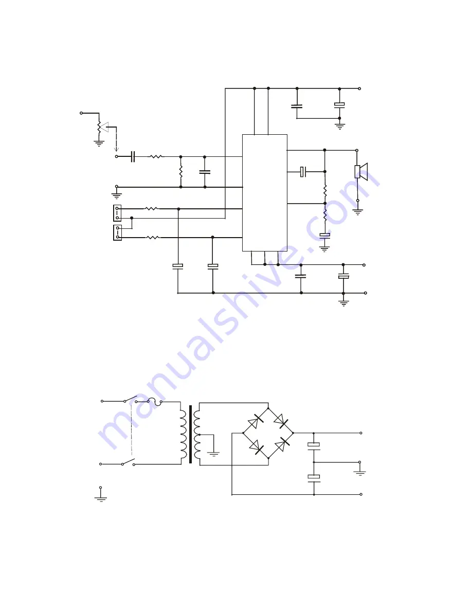
Circuit Diagram 

* Please note C6 is shown incorrectly on the 
PCB overlay. The circuit diagram is correct. 


Suggested Power supply circuit 

+

Input 

13

Speaker

(not included)

+

_

+

+

+

+

+

C1

1u5

Negative

24 - 36V

DC

IC1 

TDA 7294

2200uF 

25V

C9

2200 uF 

25V

C8

100nF

C10

100nF

C7

+

Gnd

22uF

 63V

C6

10k log Pot

Input

Attenuator

(Not Included)

.

7

R1

150R

R2

10k

C2

2n7

1

8

15

R3

10k

R4

680R

3

4

14

6

Positive

24 - 36V

DC

C3

22uF

63V

2

DC

Gnd

R5

10k

R6

22k

Mute

Standby

10

9

C4

10uF

63V

C5

10 uF

63V

Output

(optional)

.

For a stereo pair you may double the VA of the transformer, diode bridge current, 
increase capacitance and fuse rating. 
Alternatively use two complete supplies. 

A

N

E

Fuse

Switch 1a

Switch 1b

4* Diodes 5A/200V

or Diode Bridge

Mains

I/P

4700uF

50V

4700uF

50V

+

+

_

+

Gnd

35V

35V

Transformer

50V 80VA 

centre tapped

.

.

2-3A

* All grounds must connect at the same point

(+/- 25V AC)

Summary of Contents for Kit 106

Page 1: ...se one larger heatsink and mount a board at either end This is often cheaper than two smaller ones A silicon impregnated insulating washer and insulation bush are provided in the kit How it Works Most of the circuitry is contained within the IC module The input signal is applied to pin 3 via capacitor C1 and low pass filter R1 C2 The filter improves the pulse response and helps stop RF signals The...

Page 2: ...potentiometer connected as shown If you are using two modules for stereo then a dual gang pot will be required A CD player can be connected like this and will drive the module to full power without a pre amp Alternatively you might like to use one of our stereo pre amp or tone control kits The maximum continuous power you can obtain will depend largely on the size of the power supply and the size ...

Page 3: ...or Not Included 7 R1 150R R2 10k C2 2n7 1 8 15 R3 10k R4 680R 3 4 14 6 Positive 24 36V DC C3 22uF 63V 2 DC Gnd R5 10k R6 22k Mute Standby 10 9 C4 10uF 63V C5 10 uF 63V Output optional For a stereo pair you may double the VA of the transformer diode bridge current increase capacitance and fuse rating Alternatively use two complete supplies A N E Fuse Switch 1a Switch 1b 4 Diodes 5A 200V or Diode Br...

Page 4: ...Kit 106 50 Watt Audio Amplifier Page 4 of 5 Harmonic Distortion at 50W RMS 4ohms 1 kHz input Photo of completed Kit heatsink must be purchased separately ...

Page 5: ...Kit 106 50 Watt Audio Amplifier Page 5 of 5 Harmonic Distortion at 1W 1 kHz Intermodulation Distortion at 1W 250 Hz 8020 Hz 4 1 ...

Reviews: