english 13
operation.
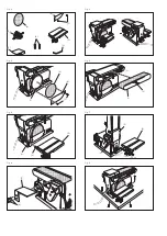
• Insert the hex key provided into the holes in the pulley
cover. Loosen the screws by turning them counterclock-
wise.
• Move the sanding belt into a vertical position as shown
in Figure 16. Vertical position can be changed using the
vertical set screw.
• Lock the sanding belt by retightening the screws. Note:
Sand long workpieces with the sanding belt in the verti-
cal position by moving the work evenly across the sand-
ing belt.
Surface sanding on the sanding belt, Fig. 17
• Hold the workpiece firmly, keeping fingers away from the
sanding belt.
• Keep the end pressed firmly against the work support
moving work evenly across the sanding belt.
Note:
Use extra caution when sanding very thin pieces and
when sanding extra long pieces, remove the work support.
Apply only enough pressure to allow the sanding belt to
remove the material.
Sanding curved pieces, see Fig. 18 and 19
WARNING:
Never attempt to sand the end pieces of a work-
piece on the idler drum. Applying the end of the workpiece
on the idler drum could cause the workpiece to fly up.
Failure to heed this warning could result in serious per-
sonal injury.
Sanding inside curves on sanding belt:
Always sand inside curves on the idler drum as shown in
Figure 18.
• Hold the workpiece firmly, keeping fingers away from the
sanding belt.
• Keep the curve pressed firmly against the idler drum
moving work evenly across the sanding belt.
Note:
Use extra caution when sanding very thin pieces and
apply only enough pressure to allow the sanding belt to
remove the material.
WARNING:
Applying the workpiece to the right side of the
sanding disc could cause the workpiece kickback. Failure
to heed this warning could result in serious personal injury.
Sanding outside curves on sanding disc:
Always sand outside curves using the sanding disc and
moving the workpiece from the left side of center as shown
in Figure 19.
• Hold the workpiece firmly, keeping fingers away from the
sanding disc.
• Keep the curve pressed firmly against the sanding disc
moving work evenly on the left side of the sanding disc.
m
Electrical connection
The installed electric motor is factory connected ready for
operation. The connection meets the applicable VDE and
DlN regulations.
The connection made by the customer as well as any exten-
sion cables used must comply with all relevant regulations.
Connection and repair work on the elctric equipment must
be carried out by a qualified technician only.
Important note
The motor rating is S 1. This means that when overloaded
it switches off automatically. After a cooling period (can
vary) you may switch it on again.
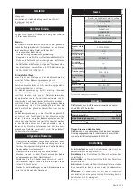
Maintenance
Warning:
When servicing use only identical replacement
parts. Use of any other parts may create a hazard or cause
product damage.
Warning:
To avoid serious personal injury make sure the
belt/disc sander is turned OFF and the cord is unplugged
from the power source before performing any maintenance
or adjustment.
General maintenance
After using your belt/disc sander, clean it completely and
lubricate all sliding and moving parts. Apply a light coat of
automotive type paste wax to the worktable to help keep
the surfaces clean.
cleansing
Frequently blow out any dust that may accumulate inside
the motor housing.
Changing drive belt, Fig. 20.
• Using a phillips head screwdriver, remove the two screws
in the center of the pulley cover.
• Remove the cover.
• Raise sanding belt to the vertical sanding position (see
Figure 20).
• Next, loosen the hex head set screw. Raising the motor
pulley releases the belt tension.
• Remove the old drive belt.
• Fit the new drive belt on the drive pulley first and then
on the motor pulley.
• Test belt tension by squeezing the belt with your fingers.
• Adjust the belt tension with the hex head set screw until
there is about 1/4 in. (6 mm) of give.
• Tighten the belt tension nut securely.
Note:
Excessive tightness on the drive belt may cause in-
creased noise and overload the motor. Excessive looseness
on the drive belt may cause the drive belt to fail prema-
turely and make a severe chattering noise.
• Using a phillips head screwdriver, reinstall the pulley
cover and the two phillips head screws. Tighten securely.
Summary of Contents for 3403301901
Page 26: ......


