background image

Document No.: KE-2015-00 


Operation and Maintenance Manual


For


A-Type Damper 

D-Type Damper 

[Wafer Type] 


Thank you for choosing KITZ products. 

For safe and trouble-free function and performance of the product, make sure to read and 

understand all items in this manual before installation and operation. Keep this manual 

accessible to all operational personnel.


Summary of Contents for KE-2015-00

Page 1: ...D Type Damper Wafer Type Thank you for choosing KITZ products For safe and trouble free function and performance of the product make sure to read and understand all items in this manual before installation and operation Keep this manual accessible to all operational personnel ...

Page 2: ...a potentially hazardous situation that if not avoided may result in minor or moderate injury and product damage Indicates a prohibited action that must not be carried out Indicates a mandatory action that must be carried out NOTES TO USERS This manual is designed to show an appropriate usage of the products for transportation storage installation operation and maintenance Be sure to read through t...

Page 3: ...ent No KE 2015 00 Contents Ⅰ Construction and Design Features 1 Ⅱ Operating Device 8 Ⅲ Transportation and Storage 11 Ⅳ Installation 14 Ⅴ Operation 18 Ⅵ Periodic Inspection 22 Ⅶ Disassembly and Reassembly 26 ...

Page 4: ...Document No KE 2015 00 1 34 Ⅰ Construction and Design Features ...

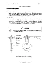
Page 5: ...r A type damper has a slightly larger disc The oval shaped disc is designed to tilt and touch the body interior hard chrome plating when the damper is in the closed position A type damper can be used for the same purpose as D type damper but its leakage rate is lower The rotation angle of the disc is between 73 and 78 when the damper is in the closed position Note that A type damper is not suitabl...

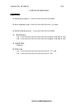
Page 6: ...ns 2 1 Maximum service pressure 0 49 MPa 2 2 Service temperature range 0 to 230 2 3 Shell test Hydraulic pressure 1 96 MPa 2 4 Allowable leakage 10A Approx 2 of rated Cv value 10D Approx 3 of rated CV value 2 5 Applicable flange JIS 5K 10K 2 6 Rotation angle 10A 73 to 78 10D 90 ...

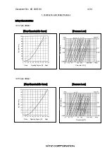
Page 7: ...tics 3 1 A type damper Flow Characteristic Curve Pressure Loss 3 2 D type damper Flow Characteristic Curve Pressure Loss Close Opening Degree Open Flow rate m3 h F l o w r a t e P r e s s u r e l o s s F l o w r a t e P r e s s u r e l o s s Close Opening Degree Open Flow rate m3 h ...

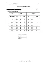
Page 8: ...Hexagon bolt nut Flange JIS 5K JIS 10K Bolt Hexagon Head Bolt Hexagon Head Bolt Nominal Size Size L Number Size L Number 50 M12 90 4 M16 100 4 65 M12 100 4 M16 110 4 80 M16 110 4 M16 120 8 100 M16 120 8 M16 130 8 125 M16 130 8 M20 140 8 150 M16 140 8 M20 150 8 200 M20 150 8 M20 160 12 250 M20 170 12 M22 180 12 300 M20 180 12 M22 190 16 第Ⅰ編 構造と機能 Hexagon Head Bolt and Nut L mm ...

Page 9: ...10K Bolt Stud Bolt Stud Bolt Nominal Size Size L Number Size L Number 50 M12 105 4 M16 120 4 65 M12 110 4 M16 125 4 80 M16 125 4 M16 130 8 100 M16 140 8 M16 140 8 125 M16 145 8 M20 160 8 150 M16 150 8 M20 170 8 200 M20 175 8 M20 180 12 250 M20 190 12 M22 200 12 300 M20 200 12 M22 210 16 Stud Bolt and Nut L mm ...

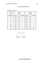
Page 10: ... pipe and the disc may contacts with the pipe When the weld flange as shown below is used select appropriate pipes in the table below shows the applicability Welding Method Welding Method A Welding Method B Schedule Schedule Pipe Type SGP 20 40 SGP 20 40 50A 2B 65 2 1 2 80 3 100 4 125 5 150 6 200 8 250 10 300 12 Welding method A B Disc Weld flange ...

Page 11: ...Document No KE 2015 00 8 34 Ⅱ Operating Device ...

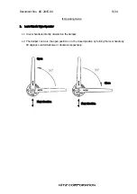
Page 12: ...e Type Operator 1 1 A lever handle is directly mounted on the damper 1 2 The damper can be in the open position or in the closed position by turning the lever handle by 90 degrees counterclockwise or clockwise respectively Open Close Flow direction Flow direction ...

Page 13: ...rotating the handwheel clockwise to set the damper in the closed position or counterclockwise to set the damper in the open position 2 3 Handwheel operating torques vary with a number of factors such as the opening position damper sizes and working pressures 2 4 The gear operator is a device to transmit a large torque to the stem by converting the torque from the drive shaft by means of the reduct...

Page 14: ...Document No KE 2015 00 11 34 Ⅲ Transportation and Storage ...

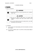
Page 15: ...roducts during transportation All damaged surfaces shall be properly repaired to prevent corrosion 2 Take care when handling and storing carton packaged products High humidity may damage the cartons and products 1 2 Transportation 1 2 1 Keep the products in their original packaging condition during transportation and until just before installation 1 2 2 Do not give any extraordinary impact on the ...

Page 16: ...jects on the products or do not step on them Overloading may damage the products 3 Do not pile up the products for storage Unstable piling may damage the products or cause personal injury 2 2 Storage 2 2 1 Store the products in a dust free low humidity and well ventilated indoor place 2 2 2 Keep the products in their original packaging and place them on pallets or racks for storage Storing product...

Page 17: ...Document No KE 2015 00 14 34 Ⅳ Installation ...

Page 18: ...ion 2 Provide adequate lighting for operation 3 Pipes shall be supported as required 4 Do not connect the damper directly with a check valve or a pump It may damage the disc by unwanted contact with the connected device 1 1 Allow sufficient room for operation installation disassembly and subsequent maintenance work with consideration for the damper size and the stem direction 1 2 Take appropriate ...

Page 19: ... to prevent the surfaces from being damaged 3 Before installation clean the connecting pipes and remove any foreign objects such as sand dust or welding spatters 4 Make sure that the flange surfaces have no damage or defects Remove any foreign objects from the flange surfaces 5 Align the upstream side and the downstream side accurately Leakage from flanged connections will be caused by inaccurate ...

Page 20: ...es Then temporarily set two bolts into the upper side of the pipe flanges 3 3 Temporarily tighten the four bolts and check that the damper is installed in the correct position 3 4 Check that the disc does not contact with the flange when the damper is in the fully open position 3 5 Attach all of the remaining bolts through the holes of pipe flanges and tighten them 3 6 Tighten the bolts evenly and...

Page 21: ...Document No KE 2015 00 18 34 Ⅴ Operation ...

Page 22: ...performed 4 Do not carelessly touch the stopper bolt of the gear unit 5 Do not excessively rotate the handwheel of the gear unit 6 Avoid using any special tools such as a pipe or a wrench for operation of the handle or the handwheel 2 Operation 2 1 Lever handle operation Damper can be set in the closed position by rotating the lever handle clockwise and in the open position by rotating the lever h...

Page 23: ...eck Soap water Replace the damper Damper body Auditory check Consult a piping engineer Loosened bolts Auditory check Retighten the bolts Abnormal noise Pipe vibration Auditory check Consult a piping engineer Loosened bolts Bolts and nuts Visual check Tactile check Retighten the bolts and nuts Excessive leakage Remove foreign objects Replace the damper Open Closed position Visual check Make sure th...

Page 24: ...s gloves and working boots 2 Take adequate safety measures against toxic inflammables or corrosive fluid 3 Reduce the line pressure to the atmospheric level before retightening flange bolts and nuts 4 1 Leakage from flange areas Tighten the bolts evenly gradually and alternatively in a star pattern as shown below ...

Page 25: ...Document No KE 2015 00 22 34 Ⅵ Periodic Inspection ...

Page 26: ...ly Inspection of this manual for details 1 4 Perform periodic inspections on dampers that are not inspected or not operated on a daily basis Periodic inspections shall be performed on all the dampers 1 5 Thorough checks are required for the dampers if a Operational failure of the damper could result in a shutdown of the entire plant unit b Fluids are highly viscous and may get stuck to and built u...

Page 27: ...uch dampers are stored or disposed of take adequate safety measures and keep the dampers separated 3 Make sure to read through the relevant actuator operation manual when an electric or pneumatic actuator is installed on the damper 4 Keep off the lifting work area to prevent personal injury due to collapsing or falling of cargo 1 Wear protective gear such as goggles gloves and working boots 2 Ensu...

Page 28: ... disc 3 When the damper is in the fully open position the disc should be parallel to the fluid flow 2 3 2 Shell tests 1 Precautions for shell test 1 Wear protective gear such as goggles gloves and working boots 2 Priority shall be given to safety when shell tests are performed 2 Shell tests Inspected dampers shall be subject to the specified hydrostatic shell test at the designated test pressures ...

Page 29: ...Document No KE 2015 00 26 34 Ⅶ Disassembly and Reassembly ...

Page 30: ...f 1 1 Precautions for disassembly 1 Take protective measures to prevent direct exposure to the fluid and catching fire 1 Wear protective gear such as goggles gloves and working boots 2 Be careful not to catch your fingers or hands during disassembly 3 Use an appropriate lifting machine when handling a large size product 1 2 Before disassembly 1 2 1 Perform disassembly in a dust free area ...

Page 31: ... to prevent misalignment Remove the lever handle nut 10 and then remove the washer 16 and the handle 9 Remove the set bolt 99A the nut 99B and the spring washer 145 and then the indicator plate 98 1 3 2 Damper with gear operator Place matchmarks on the gear unit and the damper to make the subsequent reassembly easier and to prevent misalignment Remove the set bolt 99 and then remove the spring was...

Page 32: ...s or hands during reassembly 4 Use an appropriate lifting machine for safety when handling a large size product 2 2 Before reassembly 2 2 1 Check the parts before reassembly If any unsatisfactory conditions of the parts are found replace the parts 2 2 2 Clean the reuse parts and remove dust oil and other foreign objects 2 2 3 Perform reassembly in a dust free area 2 2 4 Take care not to damage the...

Page 33: ...d gland packing 8 with a sharp pointed stick Take care not to damage the packing seal surfaces of the body and the stem 2 4 3 Select the packing with a thickness equal to or slightly larger than the half of the differential between the internal diameter of the stuffing box and the external diameter of the stem 2 4 4 With a sharp knife cut packing at an angle of 30 degrees with a length appropriate...

Page 34: ...1 Body 71 Disc bolt 3 Stem 98 Indicator plate 4 Disc 99A Set bolt 7 Gland 99B Nut 8 Gland packing 103 Bottom stem 9 Handle 117 Handle spring 10 Lever handle nut 124 Spring pin 13 Disc nut 145 Spring washer 16 Washer 157 Stop lever This illustration shows a typical construction Please refer to the approved drawing for assembly and disassembly ...

Page 35: ...Please refer to the approved drawing for assembly and disassembly Parts No Parts Name Parts No Parts Name 1 Body 98 Indicator plate 3 Stem 99A Set bolt 4 Disc 99B Nut 7 Gland 103 Bottom stem 8 Gland packing 117 Handle spring 9 Handle 124 Spring pin 10 Lever handle nut 145 Spring washer 13 Disc nut 157 Stop lever 16 Washer A Stopper pin 71 Disc bolt ...

Page 36: ...perator Type GL 10D Parts No Parts Name 1 Body 3 Stem 4 Disc 7 Gland 8 Gland packing 13 Disc nut 71 Disc bolt 99 Set bolt 102 Gear unit 103 Bottom stem 145 Spring washer This illustration shows a typical construction Please refer to the approved drawing for assembly and disassembly A A ...

Page 37: ...perator type GL 10A Parts No Parts Name 1 Body 3 Stem 4 Disc 7 Gland 8 Gland packing 13 Disc nut 71 Disc bolt 99 Set bolt 102 Gear unit 103 Bottom stem 145 Spring washer This illustration shows a typical construction Please refer to the approved drawing for assembly and disassembly A A ...

Reviews: