background image

0

/20

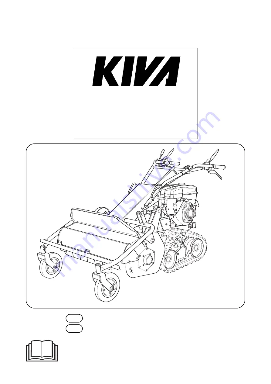
FAUCHEUSE A FLÉAUX

FLAIL MOWER

FR

Manuel d’utilisation - Notice originale

EN

Instruction for use - Original notice

- Lire les instructions du manuel utilisateur, ainsi que les consignes de sécurité. Se familiariser avec le

fonctionnement et les commandes de la faucheuse à fléaux avant utilisation.

- Read the instruction manual, and also the safety instructions. Familiarise yourself with how the flail

mower and its controls work, before using it.

696 route de Beauregard 39570 COURBOUZON

Tél. 03 84 47 03 23 - Fax. 03 84 24 61 99

E-mail : info@kiva.fr - Web : www.kiva.fr

MAXIMA


Summary of Contents for MAXIMA

Page 1: ...gnes de sécurité Se familiariser avec le fonctionnement et les commandes de la faucheuse à fléaux avant utilisation Read the instruction manual and also the safety instructions Familiarise yourself with how the flail mower and its controls work before using it 696 route de Beauregard 39570 COURBOUZON Tél 03 84 47 03 23 Fax 03 84 24 61 99 E mail info kiva fr Web www kiva fr MAXIMA ...

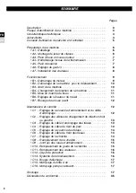
Page 2: ...B7 Blocage des roues avant Maintenance et contrôle C1 Réglage de la courroie d entraînement et du câble d embrayage C2 Réglage des câbles de changement de direction droit ou gauche C3 Réglage du câble d embrayage des fléaux C4 Réglage du câble de frein de parc C5 Réglage de la courroie des fléaux C6 Réglage du câble de frein des fléaux C7 Réglage de la chenille C8 Remplacement de la chenille C9 Jo...

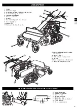
Page 3: ...A MACHINE 1 Guidon 2 Commande de gaz 3 Levier de verrouillage d embrayage des couteaux 4 Levier d embrayage des couteaux 5 Contacteur marche arrêt 6 Réservoir carburant 7 Lanceur 8 Manivelle de réglage hauteur de coupe 9 Volets de protection 10 Roues avant 11 Commande directionnelle gauche 12 Levier d embrayage avant ou arrière et frein de parc 13 Levier de vitesse 14 Grille protection d échappeme...

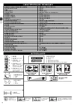
Page 4: ...illage du différentiel 160 x 60 x 25 L 0 19 Kg cm2 3 vitesses en marche avant et 1 vitesse en marche arrière Tension de la courroie 1 1 2 2 3 9 Km h 1 3 Km h 800 mm 50 à 100 mm 300 mm 46 SB 51 SB 61 SC 41 1 ère vitesse 620 m2 h 2ème vitesse 1230 m2 h 25 89 7 dBA 1 101 93 dBA 1 3 61 m s2 0 2 1 2 3 4 5 1 DANGER 2 DANGER Outils rotatifs 3 ATTENTION Lire le manuel d utilisation 4 ATTENTION Consulter l...

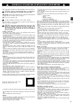
Page 5: ...problème d embrayage choc avec un objet étranger détérioration du câble d arrêt moteur arrêter le moteur immédiatement si le câble d arrêt moteur est coupé actionner la commande du starter comme décrit au démarrage moteur pour arrêter le moteur laisser la machine refroidir débrancher le fil de bougie inspecter la machine et faire effectuer les réparations nécessaires par un réparateur agréé avant ...

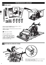
Page 6: ...ue les consignes de sécurité Se familiariser avec le fonctionnement et les commandes de la faucheuse à fléaux avant utilisation Read the instruction manual and also the safety instructions Familiarise yourself with how the flail mower and its controls work before using it A1 DÉBALLAGE A2 MONTAGE DU LEVIER DE VITESSE Ouvrir le carton d emballage de la machine et sortir la pochette de pièces illustr...

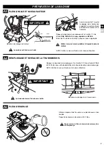
Page 7: ... transmission est livrée sans huile IMPORTANT IMPORTANT Avec la manivelle 1 ajuster le réglage de la hauteur de coupe de la machine afin de positionner le moteur à l ho rizontale Déposer le bouchon de remplissage 2 et mettre 1 1 litre d huile SAE 10W 30 d un rang supérieur à API SE Verser de l huile dans le moteur jusqu au niveau approprié Veiller à ne pas laisser pénétrer d impureté dans le moteu...

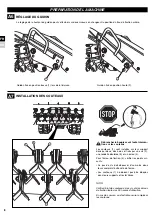
Page 8: ...on sur les couteaux Les couteaux 1 sont installés sur leur support deux par deux dos à dos et fixés par une vis 2 une rondelle dentelée 3 et un écrou 4 Pour l écrou de fixation 4 vérifier les points sui vants Le pas de vis doit dépasser d au moins deux tours complets l extrémité de l écrou Les couteaux 1 ne doivent pas être bloqués dans leurs supports et rester libres NOTA Vérifier l état des cout...

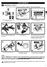
Page 9: ...que le levier d embrayage 3 est relâché sur ARRÊT Cette position active le frein de parc Placer le levier de vitesse 2 au point mort sur N B D H F Tirer vivement sur le lanceur 7 Voir NOTA ci dessous Après le démarrage du moteur placer la tirette du starter 5 sur FERMER Tourner le contacteur 6 sur ON G NOTA Après le déballage de la machine pour la première mise en route du moteur ou après une péri...

Page 10: ... les vitesses sont dif ficiles à changer Embrayer maintenir le levier d embrayage et débrayer relâcher le levier puis changer à nouveau de vitesse Si vous actionnez le levier d embrayage trop rapidement le moteur démarrera ou s arrê tera brutalement Par conséquent actionner le levier d embrayage LENTEMENT NOTA En cas de chargement sur une remorque ou sur des terrains en pente placer le levier d em...

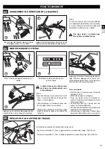
Page 11: ...vier 10 en position basse C A Appuyer sur le levier d embrayage d entraî nement 3 pour faire avancer la machine Placer le levier de régime moteur 4 sur rapide Positionner le levier de vitesse 2 à la 1ère vitesse B B6 RÉGLAGE DE LA HAUTEUR DE TRAVAIL Il s effectue en modifiant la hauteur des roues avant Tourner la manivelle 11 vers la gauche baisse la hauteur de coupe Mini 50 mm Tourner la manivell...

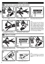
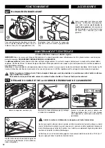
Page 12: ...e levier d embrayage 3 enfoncé à l aide d une cordelette Ajuster la tension de la courroie en agissant sur les écrous de tension 14 du câble au niveau du guidon B D 12 13 12 13 Positionner l axe 12 dans le moyeu du pivot de la roue et mettre la goupille Beta 13 Aucun accessoire n est prévu sur cette machine L utilisation d accessoires avec cette machine peut rendre la machine dangereuse et occasio...

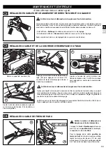
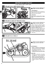
Page 13: ...C2 RÉGLAGE DES CABLES DE CHANGEMENT DE DIRECTION DROIT OU GAUCHE C3 RÉGLAGE DU CABLE ET DE LA COURROIE D EMBRAYAGE DU FLEAU C A Ajuster la tension de sorte à obtenir une flexion comprise entre 10 et 20 mm lorsque vous appuyez au centre de la courroie des couteaux Lorsque le levier d embrayage d avance ment 3 est en position basse embrayé le ressort 16 doit être libre Pour le réglage de ce câble po...

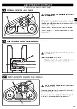
Page 14: ...e Ajuster la tension de la chenille de sorte qu elle soit la même à gauche et à droite et bloquer en position à l aide du contre écrou MAINTENANCE ET CONTROLES B Régler le câble de frein 22 des couteaux pour que la rotation des fléaux s arrête en moins de 7 secondes après avoir relâché le levier d embrayage des fléaux 10 Attention au patin 23 pour que celui ci ne colle pas à la courroie lorsque le...

Page 15: ...intervention MAINTENANCE ET CONTROLES Toutes les 100 heures d utilisation Vérifier l état du joint Spi 1 de la roue d entraînement de la chenille et en cas d anomalie remplacer le C9 JOINT SPI DES ROUES D ENTRAINEMENT 1 Arrêter le moteur et débrancher la bougie avant toute intervention Le guide de la chenille 1 est un élément sujet à l usure véri fier son état le remplacer si nécessaire Pour ce fa...

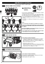
Page 16: ...nt bien fixés et vérifier l état des couteaux Lors du remplacement et du renversement des couteaux rempla cer les boulons et les écrous avec les pièces neuves 1 2 3 4 Arrêter le moteur et débrancher la bougie avant toute intervention C12 CAPOT DE PROTECTION AVANT CHAQUE UTILISATION VÉRIFIER 1 Si nécessaire remplacement des volets de protection 1 Déposer la goupille et la rondelle situées à l extré...

Page 17: ...15 NETTOYAGE DU FILTRE A AIR C16 NETTOYAGE POMPE CARBURANT Ne pas utiliser de solvant inflammable pour nettoyer l élément mousse du filtre à air 1 STOCKAGE Entreposer la machine dans un endroit sec En cas stockage durant une période supérieure à 30 jours ces opérations protégeront les élé ments de base de la machine et faciliteront la remise en service de votre machine 1 Débrayer et desserrer la t...

Page 18: ...t B7 Blocking front tires Check and maintenance C1 Pulley belt and clutch wire adjustment C2 Left or side cable adjustment C3 Tine clutch wire adjustment C4 Parking brake wire adjustment C5 Cutter pulley adjustment C6 Tine break wire adjustment C7 Crawler adjustment C8 Crawler replacement C9 Crawler wheel oil seal replacement C10 Crawler guide replacement C11 Tines replacement C12 Protection cover...

Page 19: ...ENTIFICATION PLATE 1 Handle 2 Accelerator control 3 Blades clutch lever locking 4 Blades clutch lever 5 Engine switch 6 Fuel tank 7 Recoil starter 8 Cutting height adjustment handle 9 Protection cover 10 Front tire 11 Left directing control 12 Rear or front clutch lever and parking brake 13 Shift lever 14 Exhaust protection grille 15 Crawler 16 Engine filling and level oil 17 Right directing contr...

Page 20: ... 19 Kg cm2 3 forward and 1 backward Belt tension 1 1 2 2 3 9 Km h 1 3 Km h 800 mm 50 100 mm 300 mm 46 SB 51 SB 61 SC 41 1st Shift 620 m2 h 2nd Shift 1230 m2 h 25 89 7 dBA 1 101 93 dBA 1 3 61 m s2 0 2 1 DANGER 2 DANGER Rotating blades 3 WARNING Read the ins truction manual 4 WARNING Consult the instruction manual and disconnect the spark plug before starting work 5 WARNING Do not use without protec...

Page 21: ...lem engaging or disengaging the clutch a collision with a foreign object deterioration of the motor halt cable Stop the motor immediately if the motor halt cable is severed use the starter control as described in paragraph Engine starting to stop the motor let the machine cool down unplug the spark plug lead inspect the machine and have the necessary repairs carried out by an approved repairer bef...

Page 22: ...ions du manuel utilisateur ainsi que les consignes de sécurité Se familiariser avec le fonctionnement et les commandes de la faucheuse à fléaux avant utilisation Read the instruction manual and also the safety instructions Familiarise yourself with how the flail mower and its controls work before using it A1 UNPACKING A2 SHIFT LEVER ASSEMBLY Open the cardboard packaging of the machine and take out...

Page 23: ...vel before each use The transmission is delivered without oil IMPORTANT IMPORTANT With the crank 1 adjust the regulation of the machine cutting height to position engine in horizontal Remove the filling plug 2 and fill with 1 liter of SAE 10W 30 oil upper grade than SE API class Fill with recommended engine oil up to the upper limit Watch not to let penetrate impurity into the engine NOTE Check th...

Page 24: ...igh position 2 Tines 1 are installed on metallic furniture in two back to back They are fixed with screw 2 washer 3 and nut 4 For fixing nut 4 make sure of following points At least two screws of bolt go over the end of nut Tines 1 must not be blocked in their supports and keep free NOTE Check tines screws and fixing bolts in every 30 hours of use Change tines when they are damaged or worn 1 2 3 4...

Page 25: ...his posi tion the parking brake is activated Place shift lever 2 to neutral position N B D H F Pull recoil starter 7 sharply See NOTE below After engine starting up place the starter knob 5 to CLOSE Turn engine start switch 6 to ON G NOTE After the machine unpacking during the first engine starting or after a period of remisage or win tering it is necessary to pull several tens of time on the reco...

Page 26: ...ition Engage the clutch grip the clutch lever and disengage the clutch release the clutch lever then shift again If grip the clutch lever quickly it is the reason of trouble for sudden start or sudden stop of engine So the shift lever should grip SLOWLY NOTE In case the machine is transported on a trai ler and on the slope the shift lever should be at OFF position Parking break activated B3 STOPPI...

Page 27: ...t is enough to maintain the control lever 10 in low position C A Grip the coupling clutch lever 3 to start moving Move the throttle control 4 to HIGH position Move shift lever 2 to position 1 B B6 MOWING HEIGHT ADJUSTMENT To adjust mowing height move front tires When you turn the handle 11 to the left mowing height will be lower min 50 mm When you turn the handle 11 to the right mowing height will...

Page 28: ...ch lever 3 engaged using a rope Adjust the belt tension by acting on the ten sion nuts 14 of the cable at the level of the handlebars B D 12 13 12 13 Position the axis 12 in the hub of the wheel pivot and put the Beta pin 13 No accessories are required on this machine Using accessories with this machine may make the machine dangerous and cause damage to your machine which will not be cov ered by y...

Page 29: ...EFT OR RIGHT SIDE CABLES ADJUSTMENT C3 TINE CLUTCH BELT AND WIRE ADJUSTMENT C A Adjust the bend to become between 10 to 20 mm when push center of cutter pulley belt When the forward clutch control lever 3 is in low position put into gear the spring 16 must be free For adjustment of this cable position of the control lever at the top machine stop ped adjust the tension nuts 17 so that the spring 16...

Page 30: ... Make same tension of crawler on both right and left side and then fix with lock nut CHECK AND MAINTENANCE B Adjust the tine break wire 22 in order that the tine rotation stops in 7 seconds after releasing the tine clutch lever 10 Attention to the break shoe 23 when the tine clutch lever 10 is released it should not touch to the cutter pulley belt It is important to verify the state and the wear o...

Page 31: ...ention CHECK AND MAINTENANCE Every 100 hours of use Check oil seal 1 of crawler wheel If there is any abnor mality replace with new one C9 OIL SEAL OF CRAWLER WHEEL 1 Stop the engine and disconnect the spark plug before any intervention Crawler guide 1 is a consumptive part Check and replace when it is worn To take out crawler guide remove the two bolts 2 which fix the guide 1 replace with new one...

Page 32: ...s are well fixed and tines are not lacked or damaged For safety reason replace the bolts and nuts with new ones when the replacement of tine or reversing the tine 1 2 3 4 Stop the engine and disconnect the spark plug before any intervention C12 PROTECTION COVER BEFORE EACH USE VERIFY 1 If necessary replacement of the protection flaps 1 Remove the pin and the washer situated at the end of the fixin...

Page 33: ...ANER C16 FUEL PUMP CLEANING Do not use inflammable solvents to clean the foam insert in the air filter 1 STORAGE Store the machine in a dry place If stored for over 30 days these steps will protect basic engine parts from gum deposits and will ease restoring you machine to service 1 Disengage clutch and loosen belt tension 2 Drain fuel tank strainer and carburetor Run engine until it stops Empty t...

Page 34: ...34 ...

Page 35: ...5 11 declare that the machine described below complies with the provisions of Machine Directive 2006 42 EC This machine also complies with directive 2004 108 EC Description Pedestrian operated brush cutter with petrol engine Manufacturer 1 model 2 Type 3 Brand name 4 serial number 17 sound pressure as heard by the operator 5 sound pressure as measured 6 power 10 level of vibration as felt by the o...

Page 36: ...se réserve le droit de modifier sans prévenir les spécifications de leurs machines In a permanent concern of improvement the driver clarifies that the whole of this manual is not contractual and reserves the right to modify without preventing the specifications of their machines Concept ATTRAITS GRAPHIC 05 49 71 20 62 17 ...

Reviews: