25
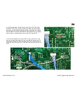
d) Fit the KiwiSix board in the same position and screw in using the four screws that
were removed from the KLM-367 in step b.
e) Plug in the cable to the KLM-366 40 pin cpu into the blue socket. Be very careful that
the pins are all in the holes before pressing in. If a pin is not in the hole it will bend and
most likely break. This will then require a replacement cable from Kiwitechnics. The
other end of this cable plugs into the Kiwisix board as shown in the photo.
f) Plug in all the cables that were removed in step a. These are best started at an angle
and then straightened as they are pushed on. This ensures that the pins go into the
socket correctly. If a plug will not go on all the way then try again until it will. Note that
the CN10 cable has moved to the center of the board and is now fitted straight up. The
brown wire goes to the right side of CN10 as viewed from the front.
VERY IMPORTANT! Make sure the plugs are correctly on ALL the pins. As it is
possible to put the plug in any position the Plug must be placed so NO pins are
visible at either end. Damage to the Polysix could occur if plugs are placed
incorrectly.
The Kiwisix Upgrade board should now look like the photo. Make sure all the cables are the correct way around and correctly on the plugs.
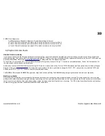
g) Plug in the midi cable to the midi connector on the KiwiSix board (CN99). This is keyed and can only be plugged in the correct way around.
h) The keyboard can now be replaced by placing it back into the Polysix and fitting the 5 screws that were removed in step 1-b. Reinsert the keyboard cable
into the socket in the KLM-366 board.
3) KLM-369 Front Panel
The Bend, Fine tune and mod wheels need a modification to make them midi
compatible. On our test Polysix we found it it difficult to remove some of the
front panel knobs without damage, Because of this instructions are given to
make the changes required with the board in place.
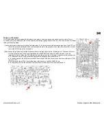
a) locate jumper J4 and R16 (470K next to J4) and R18 which are
marked with the red arrows (R18 is next to R17 and is hidden in the
photo behind the gray wires).
b) desolder these (J4, R16 & R18) and push them out of the holes
using a pin and let then fall off the board. Recover these from the
synth and remove.
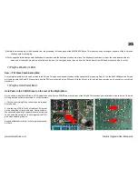
c) Locate IC2 (red arrow in right photo).
www.kiwitechnics.com
KiwiSix Upgrade User Manual v3


