38
Step 3
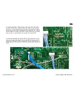
Move the plug and Sockets.
Because the plugs and sockets used in
the Polysix are made out of unobtainium and no longer available it is
necessary to remove the four sockets on the left of the board (that the
cables plug into) and the 3 pin header on the right side (that the
transformer plugs into). Desolder these and solder them into the
Upgrade power board in the same positions and the same way
around. With the printing on the board the right way up the slots in the
plugs are towards the top. Remove the two fuses by lifting at the ends
with a small screw driver, being careful not to break the glass, and put
these into the new board.
Step 4
Mount the upgrade board into the Polysix.
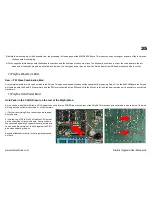
Use new heat transfer paste on the rear plate. Using the four screws that were removed in step 1 mount the upgrade
board into the Polysix. Plug in the transformer cable but not the other cables. Turn on the Polysix and adjust all the voltages in the order +15v, +5v, -15v & -5v. These
have been set at the factory but should be checked again to avoid damage to the synth. Once all the voltages are correct, switch off the Polysix and plug in the four
cable headers and solder on the blue +5v wire to the pad provided. Then switch on and readjust all the voltages again as these will change slightly under load.
Step 5
Final adjustment of the Power supply voltages.
Leave the Polysix running for at least 15mins to let the electronics warm and stabilize, then adjust each voltage to
be as close as possible to the correct voltages. This should be done in the order +15v, +5v, -15v & -5v.
Note: in the photo the extra blue +5v wire to the front panel KLM-369 board has not been fitted yet.
www.kiwitechnics.com
KiwiSix Upgrade User Manual v3


