11
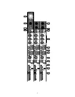
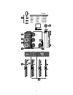
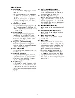
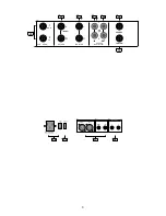
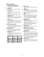
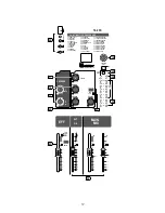
INPUT CHANNEL SECTION
1. Balanced XLR input (Mono)
Microphone input with +48 V Phantom power
(switch on rear)
2. Line input
Balanced TRS input for unbalanced and balance
line sources
3. Gain control
Adjust input signal level according to the level
meter (22).
MIC input adjust level from –60 dB ~ –16 dB
LINE input adjust level from –34 dB ~ +10 dB
4. HPF ON/OFF
The high pass filter cuts frequencies below 75 Hz
when the switch is pressed down (mono channels
only).
5. Stereo inputs
TRS jacks for unbalanced and balanced signals.
For additional mono sources use the left input. The
mono signal will be send to the right channel as
well (L/R).
6a Input sensitivity switch
Press the +4/–10 switch down to increase signal
input sensitivity for devices with low output levels
(e. g. keyboards, MP3-players).
6b Signal selector
Press the switch down to assign the channel to
the USB player (28) instead of the stereo inputs
(channel 7/8, 11/12, 15/16).
7. Equalizer (EQ)
Use the 3-band equalizer to boost (right) or cut
(left) the high, mid, and low frequencies in order to
adjust the signals.
Frequency
band
Base
frequency
Max.
boost/cut
High
12 kHz
± 15 dB
Mid
2.5 kHz
± 15 dB
Low
80 Hz
± 15 dB
8. AUX 1 and 2
AUX1 knob controls the signal level for the AUX
sends.
9. PRE switch
Press the button to send the pre-fader signal to
the AUX bus. So, the channel fader will not affect
the AUX output. Press again to send the post-fader
signal to the AUX bus.
10. Effect
Adjust the signal level, which is sent to the effect
bus. Note, that the signal level will be changed
according to the channels fader setting. Stereo
signals (L and R) will be mixed to mono and then
sent to effect bus.
11. PAN/BAL control
PAN (Panorama) controls the positioning of a mono
signal in the stereo panorama.
BAL (Balance) controls the level ratio of the stereo
channels and therefore the positioning of the
signal in the stereo panorama.
12. MUTE switch
Press to mute the channel the LED indicator will
light up at the same time.
13. PEAK (peak level indicator)
The LED lights up red when the level exceeds the
cut-off level of 3 dB.
14. SOLO switch
When the SOLO switch of a channel is pressed
down, the signal of the particular channel is sent to
the monitor and phones outputs. The SOLO MODE
indicator (27) will light up and the level meter (22)
will display the signal level of the selected channel.
This allows to monitor and to adjust the level of
single channels (pre fader listening).
15. Channel fader
The fader adjusts the output level of the signal. So,
the faders can be used to set the level ratio of all
channels.

