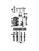
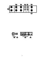
background image

15

FRONT CONNECTORS

29. Send AUX output socket 

The MON and FX jacks output the signals of the two AUX sends MON and FX. External effect or monitor 
systems can be connected.

30. RETURN L (MONO) R sockets 

The input signal oft the RETURN jacks is controlled by the RETURN control knob and is sent to the stereo bus. 
Usually the output of an external effect device (e.g. reverb and delay) is connected here; while its input is 
connected to the AUX send FX. If you only connect the RETURN L (MONO) socket the same signal is sent to the 
right channel as well. 

31. MONITOR sockets 

The jacks output the stereo signal (L/R) to a connected monitor system. The PHONES knob controls its level. 
The solo switches (14) and the Phones switch (21) determine whether the signal of the selected channel, the 
main mix or ALT 3/4 is sent to the outputs.

32. Recording output sockets (CD/Tape) 

Use the RCA sockets to connect a recording device in order to capture the mix.

33. CD/TAPE input sockets 

Use the RCA sockets to connect the outputs of the recorder or another playback device (e. g. CD/MP3 player). 
The corresponding knob in the master section controls its level (20).

34. PHONES socket 

Balanced phone-type output socket to connect headphones for monitoring. The Solo switches (14) and the 
Phones switch (21) determine whether the signal of the selected channel, the main mix or ALT 3/4 is sent to 
the output.

35. Foot switch socket 

Connect a foot switch (optional) to this jack in order to switch the internal DSP effect signal on or off.

ANSCHLÜSSE AUF DER RÜCKSEITE

36. ALT 3/4 sockets 

The jacks allow to output the mix to another system at an individual level controlled by the corresponding fader.

37. MAIN OUT (L / R) sockets 

Balanced XLR sockets to output the mix to an amplifier and loudspeaker system. 
Unbalanced Control Room jacks allow to output the mix to a monitoring system e.g.

38. Power supply 

Connect the power supply to a power outlet using the included power cord. The operating voltage is 
AC100 V~240 V for global application. Use the power switch to turn the power supply on or off.

39. Phantom power switch (48 V) 

When condenser microphones are used press the switch to turn 48 V DC phantom power on for all microphone 
inputs (XLR). Press the switch again to turn phantom power off.

Summary of Contents for 08-2 FX

Page 1: ...n das Produkt sichtbare Sch den aufweist nicht mehr ordnungsgem funktioniert ber einen l ngeren Zeitraum unter ung nstigen Umge bungsbedingungen gelagert wurde oder erheblichen Transportbelastungen au...

Page 2: ...D SEND SEND 1 1 1 MON MON MON 2 2 2 PRE PRE PRE FX FX FX PAN BAL BAL 4 MUTE MUTE MUTE dB 10 5 5 10 20 30 40 50 60 OL SOLO U U U 15 15 15 15 15 15 U U U 15 15 15 15 15 15 U U U 15 15 15 15 15 15 U U U...

Page 3: ...bestimmt den Pegel mit dem das Signal an den AUX Bus gesendet wird 9 PRE Schalter Ist der Schalter gedr ckt wird das Signal ohne Pegelsteuerung 15 an den AUX1 Bus gesendet d h die Pegelsteuerung des...

Page 4: ...BIG HALL 09 CHURCH 10 SMALL ROOM 13 MID ROOM 16 BIG ROOM 19 CHAPEL 20 PLATE 27 SPRING 30 GATED REV DIGITAL MULTI EFFECTS PHONES USB 24 BIT MULTI FX PROCESSOR POWER 16 2 FX 80 CHORUS REVERB 82 FLANGER...

Page 5: ...ge Die LEDs stellen die Pegel des linken und rechten Stereo Kanals in dB dar wobei die obersten LEDs die bersteuerung des Signals Clip anzeigen Im SOLO MODE wird der Pegel des gew hlten Kanals angezei...

Page 6: ...0V Power consumption 25W POWER ON OFF PHANTOM ON RIGHT LEFT MAIN OUT RIGHT LEFT CONTROL RM OUT 4 3 ALT 3 4OUT 36 37 38 39 1 MON R L PHONES FOOTSW 2 FX SEND AUX RETURN MONITOR MONO IN IN OUT OUT INPUT...

Page 7: ...en werden Die Pegeleinstellung erfolgt ber den entsprechenden Regler in der Master Sektion 20 34 Kopfh reranschluss Phones Symmetrischer Klinkenanschluss f r Kopfh rer zum Abh ren Die Solo Schalter 14...

Page 8: ...Q Gain 15dB Eckfrequenz H hen 12KHz Eckfrequenz Tiefen 80Hz Mittenfrequenz 2 5KHz Nennausgangspegel Main AUX Monitor 4dBu Max Ausgangsleistung 22dBu Max Eingangspegel Mikrofoneingang 12dBu Line Eingan...

Page 9: ...use Safe operation can no longer be guaranteed if the product is visibly damaged is no longer working properly has been stored for extended periods in poor ambient conditions has been subjected to any...

Page 10: ...ND SEND SEND 1 1 1 MON MON MON 2 2 2 PRE PRE PRE FX FX FX PAN BAL BAL 4 MUTE MUTE MUTE dB 10 5 5 10 20 30 40 50 60 OL SOLO U U U 15 15 15 15 15 15 U U U 15 15 15 15 15 15 U U U 15 15 15 15 15 15 U U U...

Page 11: ...knob controls the signal level for the AUX sends 9 PRE switch Press the button to send the pre fader signal to the AUX bus So the channel fader will not affect the AUX output Press again to send the...

Page 12: ...BIG HALL 09 CHURCH 10 SMALL ROOM 13 MID ROOM 16 BIG ROOM 19 CHAPEL 20 PLATE 27 SPRING 30 GATED REV DIGITAL MULTI EFFECTS PHONES USB 24 BIT MULTI FX PROCESSOR POWER 16 2 FX 80 CHORUS REVERB 82 FLANGER...

Page 13: ...ALT 3 4 24 22 Level meter LEDs display the output levels dB of the main ste reo channels L and R in order to adjust the level and avoid clipping which is indicated by the top LEDs clip In SOLO MODE t...

Page 14: ...0V Power consumption 25W POWER ON OFF PHANTOM ON RIGHT LEFT MAIN OUT RIGHT LEFT CONTROL RM OUT 4 3 ALT 3 4OUT 36 37 38 39 1 MON R L PHONES FOOTSW 2 FX SEND AUX RETURN MONITOR MONO IN IN OUT OUT INPUT...

Page 15: ...another playback device e g CD MP3 player The corresponding knob in the master section controls its level 20 34 PHONES socket Balanced phone type output socket to connect headphones for monitoring The...

Page 16: ...z Low Frequency 2 5KHz Rated Output Main AUX Monitor 4dBu Max Ausgangsleistung 22dBu Max Input Level Microphone Input 12dBu Line Input 30dBu Tape Input AUX Return 22dBu CAUTION To reduce the risk of e...

Reviews: