GL0052-03
– Envireau Mono-Tech Rainwater – Installation & Operation Guidelines
Page 16
conveniently located an alternative hole may be drilled using a proprietary hole-cutter. Do not drill this hole at
less than 300mm below ground level, to prevent freezing. In any event, the duct should be sealed into the
tank using a quality waterproof sealant. Also seal any unused hole. Run the duct in its trench with as straight
a route as possible, using the minimum number of bends with sweep-bend joints of 45 degrees maximum
only if absolutely necessary. Feed the draw wire (or rope) as the duct is laid. Use accessible joint boxes if
there is a need for an acute bend on entry into the building. Terminate the duct at a point close to, or
convenient for connection to, the control unit. The next stage is the installation of the rainwater collection
pipework.
8)
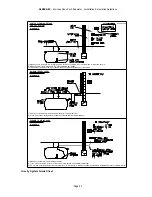
Refer to the Guide Sheet DIAGRAM B.
If you are using a
Rain Water Filter
take particular care to note the
invert levels of the pipework. The entry points are the TOP spigots of the filter, the clean water outlet is the
MIDDLE spigot and the waste water outlet is the bottom spigot. Look inside to confirm these identities. The
surface water pipework from the collection area should be jointed prior to the inlet. If a leaf filter is not
required, a manhole chamber should still be installed if only for rodding purposes in exceptional
circumstances.
Once all the collection pipework is in place, the joints should be inspected. Most drainage pipework is tested
to withstand a specified internal pressure. In Envireau systems it is important that surface water cannot seep
into the pipework under the external ground water pressure. Solvent-seal pipework is therefore preferable to
ring-seal. The next stage is the fitting of the pipework to the Control Panel.
9)
Refer to the Guide Sheet DIAGRAM B
. You are installing a GRAVITY system and so it is necessary to
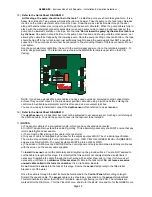
take a mains water supply feed to the HEADER TANK and to connect in (as illustrated below).
NOTE.
The illustration below does not show the weir or overflow arrangement which regulations
require
.
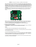
10) The ENVIREAU float shown is of the recommended FLUIDMASTER type 747.
MAINS IN
ENVIREAU IN
OFF
ON
OFF
ON
ENVIREAU
MAINS
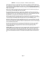
You should then couple up the incoming pump supply from the stop-cock, to the IN-LINE filter, and thence to
the Control Panel. Fit the filter as shown on the Guide Sheet, and complete the connection to the Envireau
Inlet using a Compression Fitting. Do not tighten against the spigot. Use two spanners in contra-rotation to
compress the olive and effect a seal. Do not use soldered joints under any circumstances. You may use
push-fit connections on the property side of the Control Unit but do not use push-fits anywhere on the pump
side. The next stage is the completion of the electrical connections.
11)
Refer to the Guide Sheet DIAGRAM C
. The following instructions
must be carried out by a competent,
qualified person
and must be to the relevant standards as laid down in the current IEE regulations. Failure to
carry out this work to the required standards may cause system malfunction, damage or costly repairs. It
could also cause injury or death.
BE SAFE.
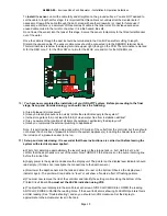
The incoming electrical supply should be installed first, all in accordance with the Guide Sheet.
12)
Refer to the Guide Sheet DIAGRAM C
. The
main electrical supply
should come from either the
Distribution Board, fused or with MCB Type C rated 16 amps, thence via a separate Residual Current
Detector (RCD),
or
from a local switched fused spur with integral RCD. Remove the control unit lid and


