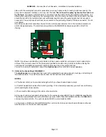
GL0052-03
– Envireau Mono-Tech Rainwater – Installation & Operation Guidelines
Page 26
18)
You have now completed the installation of your DIRECT system. Before proceeding to the final
stage, Set-up and Commissioning, you should check the following.
a) Are all pipework joints secure?
b) Have you taken precautions to quickly isolate the electrical supply to the system?
c) Is the storage tank full (or at least half-full) of clean water, free from installation detritus?
d) Are you aware of the location of all items of equipment, particularly the DISPLAY unit?
e) Have you COMPLETED the external plumbing to appliances?
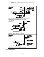
Note. It is permissible to install a stop-cock within 0.5 metres of the outlet from the controller but there should
not be less than 3metres of pipework in total to the system appliance(s) without the inclusion of a
PRESSURE VESSEL in the run
.
19)
Set-up and commissioning. IT IS ESSENTIAL THAT THESE INSTRUCTIONS ARE CARRIED OUT
BEFORE LEAVING THE SYSTEM WITH ELECTRICAL POWER APPLIED.
a)
First of all, determine approximately the level of water in the storage tank i.e. Full, Half-full, etc. and
confirm that the depth sensor is out of the water. Now TURN OFF the stop-cock on the pump incoming
line before the in-line
filter and turn off the mains water stop-cock.
b)
Apply power to the system and observe the display unit. the pointer on the display level indicator
should read empty. (If it does not, investigate the connections to the depth sensor.)
c)
Now lower the depth sensor into the tank and allow it to rest on the bottom. Observe the display level
indicator again. The pointer will read either a “level” or will show a “fan-like” effect of flashing pointers.
d)
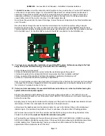
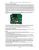
You must now remove the lid of the control panel and identify the setting controls along the bottom of
the Printed Circuit Board.
You must set the LEVEL indication using VR2.
e)
To adjust the level display turn the small brass set-screw of VR2 CLOCKWISE to LOWER the
reading, ANTI-CLOCKWISE to RAISE the reading. Note. If the Level Indicator is showing FLASHING
pointers this is a HIGH reading (See “Troubleshooting”) and so you should turn VR2 clockwise. Set the
display to approximate to the actual water level in the tank.
f)
Now remove the filter from the in-line filter carrier on the pump incoming pipe and VERY SLOWLY
open the incoming stop-cock below the filter carrier. You will hear AIR rushing up the pipe from the
pump. Be ready to turn off the stop-cock to avoid spillage from the filter carrier. Turn off the stop-cock
when water wells up inside the filter carrier. Replace the filter and screw the parts together firmly.
NOW
OPEN THE STOP-COCK FULLY. CHECK FOR LEAKS.
g)
Observe the display unit. The STATUS light may be illuminated. Ignore this indication during setting
up.
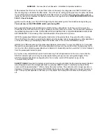
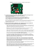
You must now set the pressure switch point using VR8.
h)
To set VR8, the pressurised indicator must first of all be extinguished. To do this you will now set the
PUMP SWITCH-OFF pressure to a higher pressure than the pump can achieve. The pressurised
indicator is the GREEN light nearest to VR8. TURN VR8 ANTI-CLOCKWISE UNTIL THE
PRESSURISED INDICATOR EXTINGUISHES. If it is already unlit at initial observation then proceed to


