background image

GL0052-03

 – Envireau Mono-Tech Rainwater – Installation & Operation Guidelines 


Page 6

NON-STANDARD SYSTEMS  
 

Finally, please note there are also available a number of non-standard systems.


You should have consulted 

with ENVIREAU and be fully familiar with your own requirements, particularly regarding EXTRA items of 
equipment. You should be 

aware

 of your requirements regarding 

NON-STANDARD SYSTEMS before 

commencing installation.


If you are 

UNSURE 

of these requirements 

READ THE RELEVANT INSTRUCTIONS IN THE NON-

STANDARD SYSTEMS document

.  

 
The additional document entitled 

NON-STANDARD SYSTEMS

 will cover the following:  


a)   Interfacing with Building Management Systems (BMS) 
b)   PUMP LOCK-OUT MODE (A pump protection mode) 
c)   AUTO-STANDBY PUMP MODE (MUST BE PRE-ORDERED) 
d)   PUMPED OVERFLOW MODE (for systems with NO overflow from the tank. MUST BE PRE-ORDERED but 

ONLY if using a DIRECT SYSTEM as an extra solenoid valve is required) 

e)  HIGH LIFT PUMPS and the use of contactors (MUST BE PRE-ORDERED). 
f)  HIGH-FLOW BYPASS systems (MUST be pre-planned and understood). 
g)  UV SYSTEMS. These systems are outlined in this section but you should refer to the manufacturer’s data for 

specific details (MUST BE PRE-ORDERED). 

 
Very Important:  Whichever system you intend installing, there is a commissioning requirement to 
set-up the SYSTEM PRESSURE OPERATING POINT. This will be explained specifically in the 
instructions.  
 
NEVER LEAVE A SYSTEM POWERED UP WITHOUT CARRYING OUT THIS PROCEDURE.  
Failure to carry out this essential setting-up can result in non-operation, damage or excessive 
electricity consumption.  

 
For the purposes of this Instruction Manual, it is assumed that you have installed the Rain Water Holding 
Tank and Rainwater Filter in accordance with the instructions supplied with that product. 
To assist you in your work scheduling you should read the 

GENERAL

 notes below. Full details are given in 

the relevant sections, but it is worth noting these points 

IN ADVANCE. 

Summary of Contents for Envireau GL0052K

Page 1: ...eau Mono Tech Rainwater Recovery System Installation Operation Guidelines Klargester Environmental College Road North Aston Clinton Aylesbury Buckinghamshire HP22 5EW Tel 44 0 1296 633033 Fax 44 0 1296 633001 Website www klargester com Email sales klargester com ...

Page 2: ...cutting GRP components Access covers should be selected with reference to the location of the unit and traffic loads to be accommodated These are not normally part of the units supply When covers are removed precautions must be taken against personnel falling into the unit Should you wish to look into the tank please observe all necessary precautions including those listed below which apply to mai...

Page 3: ...very Systems 1 N 9 02 05 Marking Identification of Pipework This document lists the requirements of the Water Company for the installer to ensure that all of the pipework and appliances used to carry and deliver the reclaimed water are clearly marked to ensure that all users now and in the future can easily see the difference between the mains water and reclaimed water system In short all tap poin...

Page 4: ...lter are covered by separate installation instructions The installation of ancillary equipment is covered by the manufacturer s own installation instructions Please ensure that the installation is carried out in accordance with the relevant regulations for that part of the procedure Building Regulations Planning Requirements Electrical Regulations Water Regulations Etc For assistance or further in...

Page 5: ...them SAFE and be certain of what type of system you wish to install There are THREE possibilities GRAVITY DIRECT or NO MAINS To help clarify the types of installation read below 1 Do you intend using a HEADER TANK If you do then you should follow the instructions for the installation of a GRAVITY system Discard the instructions for the DIRECT and NO MAINS system Note also that you do not require t...

Page 6: ...YSTEM as an extra solenoid valve is required e HIGH LIFT PUMPS and the use of contactors MUST BE PRE ORDERED f HIGH FLOW BYPASS systems MUST be pre planned and understood g UV SYSTEMS These systems are outlined in this section but you should refer to the manufacturer s data for specific details MUST BE PRE ORDERED Very Important Whichever system you intend installing there is a commissioning requi...

Page 7: ...peration As in any pressurised plumbing system a correctly sized Pressure Vessel Expansion Vessel should be installed The vessel supplied by others should be installed between the Control Panel and the appliances We would be happy to assist with size selection but as a guide the vessel should be equal in capacity to at least 50 of the appliance storage capacity e g 5 toilet cisterns x 6 litres 30 ...

Page 8: ...for further advice The following instructions up to and including Item 9 involve essentially Civil and Plumbing work The ELECTRICAL INSTALLATION begins at Item 10 Once you are confident in your choice of locations you should begin by laying in the pipework and electrical ducts as shown on the Guide Sheet The collection pipes should be a minimum of 110mm and should be connected to the roof drainpip...

Page 9: ...urface water cannot seep into the pipework under the external ground water pressure Solvent seal pipework is therefore preferable to ring seal The next stage is the fitting of the pipework to the Control Panel 9 Refer to the Guide Sheet DIAGRAM B You are installing a NO MAINS system and so it is only necessary to couple up the incoming pump supply from the stop cock to the in line filter and thenc...

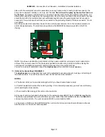
Page 10: ...l unit Printed Circuit Board Note If you wish to use the PUMP LOCK OUT MODE or BMS contact on the display unit and you need to bring the feed from the contact back into the same location as the control unit use 6 core cable The two remaining cores go into the pair of terminals at the back of the display unit See the document on NON STANDARD SYSTEMS for details of the BMS CONNECTIONS and PUMP LOCK ...

Page 11: ...fication is 4 core 16 0 2mm per core red yellow green blue or numbered screened by braid or SWA The outer insulation must be rated at 240v rms e the screen or SWA must be earthed at the control unit end only and must be electrically continuous with the screen on the sensor cable supplied To install the sensor uncoil the cable fully and straighten on the ground surface You are not advised to cut th...

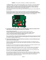
Page 12: ... on the bottom Observe the display level indicator again The pointer will read either a level or will show a fan like effect of flashing pointers d You must now remove the lid of the control panel and identify the setting controls along the bottom of the printed circuit board You must set the level indication using VR2 e To adjust the level on the display unit turn the small brass set screw of VR2...

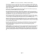
Page 13: ... You have now completed set up and commissioning Test all appliances and check to ensure that the STATUS indicator light RED which may have illuminated during set up has now extinguished again If the STATUS indicator light fails to extinguish within five minutes switch off the system and go to the Troubleshooting section SAFETY CHECK Now that the system is commissioned you should check that the pu...

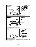
Page 14: ... MAINS SYSTEM DIAGRAM B RAINWATER RECOVERY NO MAINS SYSTEM DIAGRAM A NO MAINS SYSTEM PUMP PLUMBING DETAILS 1 Check your invert levels in advance particularly if using a leaf filter 2 Make sure that no surface water or debris enters the tank during installation 1 Make duct suitable for free drawing of cables 2 If you must join cables joint out of the turret Joints should be completely watertight 3 ...

Page 15: ...tion please contact ENVIREAU for further advice The following instructions up to and including Item 9 involve essentially Civil and Plumbing work The Electrical Installation begins at Item 10 Once you are confident in your choice of locations you should begin by laying in the pipework and electrical ducts as shown on the Guide Sheet The collection pipes should be 110mm and should be connected to t...

Page 16: ...nt seal pipework is therefore preferable to ring seal The next stage is the fitting of the pipework to the Control Panel 9 Refer to the Guide Sheet DIAGRAM B You are installing a GRAVITY system and so it is necessary to take a mains water supply feed to the HEADER TANK and to connect in as illustrated below NOTE The illustration below does not show the weir or overflow arrangement which regulation...

Page 17: ... cable This cable should be four cores at 1 amp per core rating 7 0 2 mm each core Core colours red yellow black blue The cable should be connected between the terminal block on the back of the display unit to the terminal block marked DISPLAY in the control panel The terminal blocks at both ends are marked R for RED core Y for YELLOW core Bu for BLUE core and Bk for black core The terminal block ...

Page 18: ...uctors to achieve this you must convert to the previously specified cable size using a joint box before entering the control panel A suitable pump isolator switch is often used as a convenient joint box You are now ready to install and connect the depth sensor often referred to as just sensor 15 Refer to the Guide Sheet DIAGRAM C The depth sensor is a robust item but must not be subjected to exces...

Page 19: ... aware of the location of all items of equipment particularly the display unit e Have you completed the external plumbing to appliances Note It is permissible to install a stop cock within 0 5 metres of the outlet from the controller but there should not be less than 3 metres of pipework in total to the system appliance s including the header tank without the inclusion of a pressure vessel in the ...

Page 20: ... is the case by operating the ball cock in the header tank or by operating any other appliances on the same feed e g external taps Allow the header tank to FILL and the DEMAND to cease j NOW turn VR8 clockwise until the pressurised indicator illuminates You may turn VR8 up to 3 turns past this point to ensure pump switch off on pressurisation but if you turn the control too far the pump may fail t...

Page 21: ...NG RUNS DIAGRAM C GRAVITY SYSTEM DIAGRAM B RAINWATER RECOVERY GRAVITY SYSTEM PUMP PLUMBING DETAILS DIAGRAM A GRAVITY SYSTEM 1 Check your invert levels in advance particularly if using a leaf filter 2 Make sure that no surface water or debris enters the tank during installation 1 Make duct suitable for free drawing of cables 2 If you must join cables joint out of the turret Joints should be complet...

Page 22: ...n of the Control Panel Note that this unit should be mounted under cover protected from frost and be located at a convenient height of between 1 5 metres and 2 4 metres above GROUND level If you wish to mount the unit in any other location please contact ENVIREAU for further advice The following instructions up to and including Item 9 involve essentially Civil and Plumbing work The Electrical Inst...

Page 23: ...refore preferable to ring seal The next stage is the fitting of the pipework to the Control Panel 10 Refer to the Guide Sheet DIAGRAM B You are installing a DIRECT system and so it is necessary run the mains water supply through a stop cock and then to the supplied solenoid valve The location of the solenoid valve is not relevant but it should be accessible and convenient for Electrical connection...

Page 24: ...nal block on the back of the display unit to the terminal block marked DISPLAY in the control panel The terminal blocks at both ends are marked R for RED core Y for YELLOW core Bu for BLUE core and Bk for black core The terminal block is marked DISPLAY and is top right facing on the control panel Printed Circuit Board Note If you wish to use the PUMP LOCK OUT MODE or BMS contact on the DISPLAY uni...

Page 25: ...t sensor 16 Refer to the Guide Sheet DIAGRAM C The depth sensor is a robust item but must not be subjected to excessive impact crushing or stretching of the attached cable To avoid these occurrences it is the last item to be installed 17 NOTES a The sensor cable is of a pre ordered length which you have checked upon receipt b It is NOT advisable to extend this cable by jointing If it is absolutely...

Page 26: ...o the tank and allow it to rest on the bottom Observe the display level indicator again The pointer will read either a level or will show a fan like effect of flashing pointers d You must now remove the lid of the control panel and identify the setting controls along the bottom of the Printed Circuit Board You must set the LEVEL indication using VR2 e To adjust the level display turn the small bra...

Page 27: ...oned i e with a high top up switch on point cause topping up to continue EVEN THOUGH THE TANK IS FULL causing water to flow out of the overflow continuously without the level increasing sufficiently to reach the turn off point This will waste considerable water if not detected v If you set VR7 too low you may find that the system responds to very small level changes as may be caused by ripples on ...

Page 28: ...rage tank falls to a very low EMPTY level To do this you should turn off the mains stop cock and lift the sensor until it is approximately 7 18mm below the water surface The pump should no longer operate on demand at this level and the opening of any attached appliances will not cause the pump to start IF THE PUMP STILL OPERATES AT THIS LEVEL you may adjust VR5 slowly anti clockwise until the pump...

Page 29: ...2 Make sure that no surface water or debris enters the tank during installation 3 Do not fix the Tundish device above electrical equipment 4 Try to take the mains water supply from the furthest system point to avoid diverting when topping up the outside tank 1 Make duct suitable for free drawing of cables 2 If you must join cables joint out of the turret Joints should be completely watertight 3 Do...

Page 30: ...ng tank System Depressurised Alarm Permanent STATUS indication NOTE Under high discharge rate conditions and with pressure adjustment control set slightly high it is possible that a temporary alarm indication will occur This is normal and is an indication that water has been discharging at a high rate for and extended period The alarm condition will cancel when the discharge reduces or stops The a...

Reviews: