18
DM8000 User Manual
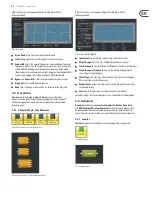
Right-click to access the Component Object’s Dialog Box, with the
following controls:
Matrix Mixer Dialog Box
•
Mute In
turns the input signal on or off .
•
Level In
adjusts the relative input volume. Left-click to adjust levels.
•
Assign Matrix
assigns inputs to specifi c outputs.
•
Mute Out
turns the output signal on or off .
•
Level Out
adjusts the relative output volume.
3.2.4 Matrix w/delay
Matrix w/Delay
adds a delay feature but otherwise functions like the
Matrix Mixer.
Matrix w/Delay Module Icons
Matrix w/Delay Component Objects
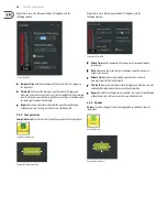
Right-click to access the Component Object’s Dialog Box, with the
following controls:
Matrix w/Delay Dialog Box
•
Mute In
turns the input signal on or off .
•
Level In
adjusts the relative input volume. Left-click to adjust levels.
•
Assign Matrix
assigns inputs to specifi c outputs.
•
Mute Out
turns the output signal on or off .
•
Level Out
adjusts the relative output volume. Left-click to adjust levels.
•
Delay
adjustment is same as level adjustment.
3.2.5 room Combiner
The Room Combiner module acts as a router that can manage audio streams
routing and control of combinable/divisible spaces. This module can support
a maximum of 16 rooms in numerous configurations, with combinable levels,
muting and source tracking. Logic inputs and outputs are provided for wall state
and source selection, as well as the ability to combine and control the function of
Auto Mixer modules connected to the Room Combiner module’s inputs.
When a Room Combiner module is dropped into the Build Window, the software
will automatically launch a Parameter Dialog Box:
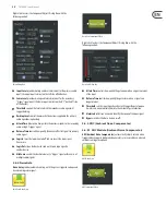
Room Combiner Initialisation Dialog Box
In the Dialog Box, Room Combiner uses a 16x16 grid of blocks to lay out
graphically the relative position of each room. Adjacent, enabled blocks in
the grid can have three types of walls: permanent, removable and none.
The wall type is selected by repeatedly clicking on the border between adjacent
enabled blocks.
•
Clear All
button removes all blocks from the grid.
•
Enable Wall Logic
controls whether the Room Combiner Component Object
will have logic connections for wall state.
•
Enable Source Logic
determines whether logic connections for source
selection will appear on the Component Object.
Please keep in mind the following points:
•
Removable walls are indicated by a thin dashed line, and the removable wall
will have a corresponding logic node on the block.
•
Permanent walls are indicated by a thick gray line that represents a non-
removable border between those rooms. A permanent wall will not have a
logic connection on the block.
•
No border between adjacent enabled blocks indicates there is no wall, and
the adjacent enabled blocks are therefore considered part of the same space.
Summary of Contents for DM8000
Page 65: ......


