Operating Instructions KLAROconnect
Status 06/2022
KLARO GmbH
Page 6/21
3.2 Scope of delivery
970716Additional package KLAROconnect indoor antenna I-cabinet PP, A-cabinet PP
970717Additional package KLAROconnect indoor antennaI-cabinet1/2/3, A-cabinet4/5, M-technology
970718Additional package KLAROconnect indoor antenna A-Uni. / -pillar
970719Additional package KLAROconnect external aerialA-cabinet3/4/5/uni / column
Article Quantity Designation
970716 970717 970718 970719
901471 1 STK KLAROconnect
●
●
●
●
982223 1 STK Data cable
●
●
●
●
901474 1 STK LTE indoor antenna
●
●
●
●
901476 1 STK LTE outdoor antenna
○
○
○
●
980194 10 CM Velcro tape
●
●
●
●
901475 1 STK Ethernet extension cable
●
○
○
○
980314 1 STK Cable gland M16
○
●
○
●
980311 1 STK Locknut M16
○
●
○
●
● Included in the
scope of delivery
○ not
included in the scope of delivery
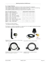
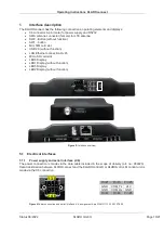
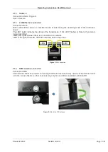
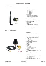
The following is a pictorial representation of components from the KLARO WebMonitor® packages
(Velcro tape, cable gland and locknut are not shown).
Illustration 1
901474 LTE indoor antenna with tilt joint (always
included as standard)
Picture 2
901476 LTE outdoor antenna SMA 4G
Illustration 3
901475 Ethernet extension cable FTP Cat6 right-
angled 0.5m (as standard for I-cabinet PP)
Illustration 4
982223 Data cable KLAROconnect
KLAROcontrol.S/M
Operating Instructions KLAROconnect
Status 06/2022
KLARO GmbH
Page 7/21
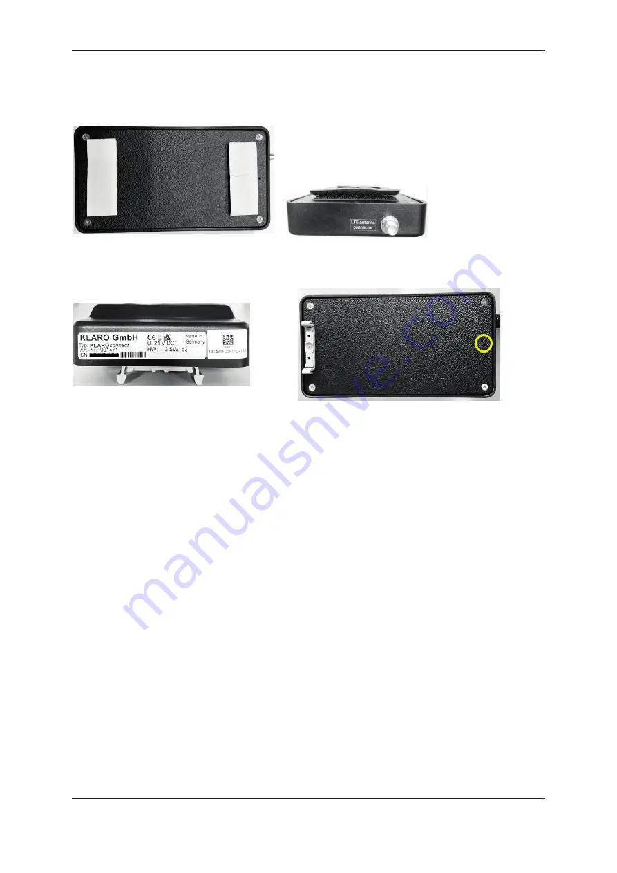
3.3 Mounting KLAROconnect
3.3.1 Velcro fastening
The Velcro tape included with the KLAROconnect is used
to mount the communication module.
Note: The glued areas must be made dust-free before
applying the Velcro tape.
3.3.2 Mounting adapter (available from WAGO)
The KLAROconnect can be mounted on a DIN 35 rail using two mounting feet (WAGO 209-123). To
do this, the mounting feet are mounted with the screws on the underside in the holes provided.
Summary of Contents for 970716
Page 23: ......


