KLARO GmbH
22
Original Operating Manual for KLARO Small Wastewater Treatment Plant V.15.07
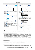
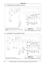
Control KLbasic/KL24base
Control KLplus/KL24plus
operating parameters may also be changed using a certain action code. This second maintenance
level is exclusively reserved for qualified personnel!
Unauthorized changes to the control settings will void the warranty!
5.4.
Changing the Fuses
Before replacing the fuses, the system must be switched off, using the red maintenance
switch!
To change or to check the fuses, the control and machine cabinet must be opened with the supplied
key.
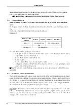
On the back of the controller are the microfuses described above.
Fuses used:
Microfuse 230
V/50 Hz
KLbasic
KLplus
KL24plus
KL24base
Supply F1
8 A, medium time-
lag,
6.3 A, delay-action
Consumer F2
2 A, delay-action
-
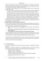
To replace the microfuses, please proceed as follows:
–
Under light pressure, turn the head of the holder a quarter turn to the left (counter-clockwise),
using a slotted screwdriver SL 1.0 x 5.5.
–
Remove the head of the holder with the fuse
–
Replace the fuse
–
Insert the head with the fuse in the opening of the holder
–
Lightly press on the head of the holder with a screwdriver and lock the fuse by turning the head
a quarter turn to the right (clockwise).
Note:
If you cannot resolve the issue, please contact your maintenance company or KLARO as soon
as possible.
5.5.
Operation of Power Failure Detector
The controller is equipped with a power failure detector, which is fed by an integrated emergency power
supply (buffering). Upon delivery, the emergency power supply is empty. It charges up after switching on
the controller. In the event of a power failure, the charge of the emergency power supply for signalling
the power failure lasts for about 12 hours. If the emergency power supply is not used by power failures,
the circuit prevents the discharging of the emergency power supply.
Important:
In the event of a power failure, the time/date settings are supplied with power by an extra
buffer for about 10 days. All stored data, such as operating hours, program settings, etc., is saved.
However, if no time and date is set, no weekly operating hours of the units will be saved. Future fault
messages will be saved with an incorrect date.
KLARO GmbH
Original Operating Manual for KLARO Small Wastewater Treatment Plant V.15.07
23
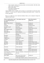
If the system is disconnected from the mains (e.g., due to power failure, a blown internal fuse, or
disconnection from the power outlet), the warning device alternately gives an acoustic and optical signal,
regardless of the cause. The device responds to a power failure with a delay of 5 seconds. This avoids
that short failures, such as those that often occur during a thunderstorm and that do not affect the overall
function of the wastewater treatment plant, are not signalled unnecessarily.
-
After a 5 sec delay, an intermittent beep with red flashing signal is emitted. At intervals of 5
seconds, five flashing signals with a beep continue being emitted for approximately 12 hours
(when the emergency power supply is fully charged).
-
A shutdown of the unit is not possible in this state.
When the mains voltage returns, the device goes back to the monitoring state without requiring any key
to be pressed and the controller runs where it left off on. The fault message disappears automatically. If
the emergency power supply is discharged, the operation restarts with a cycle pause.
Power
Failure
Attention:
If the system is disconnected from the mains for more than 24 hours, treatment
of the existing wastewater is no longer possible, or possible only to a very limited extent.
Never switch off the plant
(with the exception of maintenance of plant components and
malfunctions of the plant affecting its functions)
6.
Additional functions of the Controllers KLplus/ KL24plus and KLbasic/KL24base
6.1.
Underload detection (KLplus/KL24plus)
Malfunction
Attention: Activation of level-dependent operation must be carried out by a service
engineer or an expert. Incorrect calibration of the system can cause the system to run
in economy mode (cycle pause) permanently! Proper treatment is not possible in that
case!
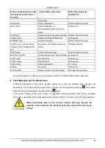
On delivery, this function is deactivated. When commissioning, the plant runs in automatic mode
regardless of the amount of the incoming wastewater.
It is recommended to enable this feature no
earlier than after a running-in period of 3 months!
The KLplus controller is equipped with a pressure
sensor by default, which can determine the level in the first chamber. This function is used to save
energy in case of low wastewater inflow.
KLARO GmbH
2
Original Operating Manual for KLARO Small Wastewater Treatment Plant V.15.07
IMPORTANT:
•
This Operating Manual contains information about the plant, from installation
to maintenance, and must therefore be read before commissioning of the
plant!
•
All safety instructions must be observed!
•
The Operating Manual must be kept readily available during the operation of
the plant!
Plant Specifications
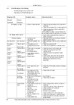
For any questions in the course of the operation of the plant, the specifications of your plant should
be noted as follows. With the help of this information, our staff will be able to help you more quickly
in the event of a malfunction. The specifications can be found on the nameplate, which is located
on the outside of the cabinet door for indoor cabinets, and inside the cabinet for outdoor cabinets.
Small Wastewater Treatment
Plant
PT
Sludge storage
Buffer
SB-Reactor
Approval No.:
Process class:
Certified:
Cabinet:
Controller:
Compressor:
Denomination:
Serial No.:
Article No.:
Additional module:
Article No.:
El. Connected load:
KLARO GmbH
Original Operating Manual for KLARO Small Wastewater Treatment Plant V.15.07
3
CONTENTS
Page
1.
About this Operating Manual
6
1.1.
Original Language of Documentation
6
1.2.
Completeness
6
1.3.
Liability
7
2.
Safety
7
2.1.
Explanation of Warnings and Prohibitions
7
2.2.
Hazard statements
8
2.3.
Warnings
9
2.4.
Exclusion for Use
10
3.
Warranty
10
4.
Function of the SBR Plant
10
4.1.
Plants for carbon elimination (process classes C)
11
4.2.
Systems with Additional Nitrogen Removal (Process Classes N and D)
13
4.3.
Systems with Additional Phosphate Elimination (Process Class +P)
13
4.4.
Systems with Additional Sanitation (Process Class +S)
13
5.
Control of the Small Wastewater Treatment Plant
13
5.1.
Connections to the KL-controls (230V option for solenoid valves)
16
5.2.
Connections to the KL24 controller(24V option for stepper motor valves)
16
5.3.
Operating the Controller
18
5.3.1.
Querying Operating Hours
18
5.3.2.
Manual Control of the Valves and the Cabinet Fan in "Manual Mode"
19
5.3.3.
Setting Date/Time
20
5.3.4.
Set Holiday Mode
20
5.3.5.
Query Malfunctions - Query Old Malfunctions
21
5.3.6.
Display Settings
21
5.3.7.
Service Menu and Action Code
21
5.4.
Changing the Fuses
22
5.5.
Operation of Power Failure Detector
22
6.
Additional functions of the Controllers KLplus/ KL24plus and KLbasic/KL24base
23
6.1.
Underload detection (KLplus/KL24plus)
23
6.1.1.
Mode of Operation
24
6.1.2.
Commissioning
24
6.1.3.
Switching Off the Level Measurement
25
6.1.4.
Safety and Fault Messages
25
6.2.
Optional Functions
26
6.2.1.
Connection of an external alarm device
26
6.2.2.
Connection of a contactor for switching the compressor
26
6.2.3.
Connection of a UV reactor
26
6.2.4.
Phosphate precipitation with metering pump
26
7.
Maintenance, Repair and Operation
28
7.1.
Sludge Evacuation
28
7.2.
Operating Instructions
29
8.
Fault Messages and Troubleshooting
31
8.1.
Fault Message on the Display
32
8.2.
Unusual Water Levels - Troubleshooting
33
KLARO GmbH
2
Original Operating Manual for KLARO Small Wastewater Treatment Plant V.15.07
IMPORTANT:
•
This Operating Manual contains information about the plant, from installation
to maintenance, and must therefore be read before commissioning of the
plant!
•
All safety instructions must be observed!
•
The Operating Manual must be kept readily available during the operation of
the plant!
Plant Specifications
For any questions in the course of the operation of the plant, the specifications of your plant should
be noted as follows. With the help of this information, our staff will be able to help you more quickly
in the event of a malfunction. The specifications can be found on the nameplate, which is located
on the outside of the cabinet door for indoor cabinets, and inside the cabinet for outdoor cabinets.
Small Wastewater Treatment
Plant
PT
Sludge storage
Buffer
SB-Reactor
Approval No.:
Process class:
Certified:
Cabinet:
Controller:
Compressor:
Denomination:
Serial No.:
Article No.:
Additional module:
Article No.:
El. Connected load:
KLARO GmbH
Original Operating Manual for KLARO Small Wastewater Treatment Plant V.15.07
3
CONTENTS
Page
1.
About this Operating Manual
6
1.1.
Original Language of Documentation
6
1.2.
Completeness
6
1.3.
Liability
7
2.
Safety
7
2.1.
Explanation of Warnings and Prohibitions
7
2.2.
Hazard statements
8
2.3.
Warnings
9
2.4.
Exclusion for Use
10
3.
Warranty
10
4.
Function of the SBR Plant
10
4.1.
Plants for carbon elimination (process classes C)
11
4.2.
Systems with Additional Nitrogen Removal (Process Classes N and D)
13
4.3.
Systems with Additional Phosphate Elimination (Process Class +P)
13
4.4.
Systems with Additional Sanitation (Process Class +S)
13
5.
Control of the Small Wastewater Treatment Plant
13
5.1.
Connections to the KL-controls (230V option for solenoid valves)
16
5.2.
Connections to the KL24 controller(24V option for stepper motor valves)
16
5.3.
Operating the Controller
18
5.3.1.
Querying Operating Hours
18
5.3.2.
Manual Control of the Valves and the Cabinet Fan in "Manual Mode"
19
5.3.3.
Setting Date/Time
20
5.3.4.
Set Holiday Mode
20
5.3.5.
Query Malfunctions - Query Old Malfunctions
21
5.3.6.
Display Settings
21
5.3.7.
Service Menu and Action Code
21
5.4.
Changing the Fuses
22
5.5.
Operation of Power Failure Detector
22
6.
Additional functions of the Controllers KLplus/ KL24plus and KLbasic/KL24base
23
6.1.
Underload detection (KLplus/KL24plus)
23
6.1.1.
Mode of Operation
24
6.1.2.
Commissioning
24
6.1.3.
Switching Off the Level Measurement
25
6.1.4.
Safety and Fault Messages
25
6.2.
Optional Functions
26
6.2.1.
Connection of an external alarm device
26
6.2.2.
Connection of a contactor for switching the compressor
26
6.2.3.
Connection of a UV reactor
26
6.2.4.
Phosphate precipitation with metering pump
26
7.
Maintenance, Repair and Operation
28
7.1.
Sludge Evacuation
28
7.2.
Operating Instructions
29
8.
Fault Messages and Troubleshooting
31
8.1.
Fault Message on the Display
32
8.2.
Unusual Water Levels - Troubleshooting
33
23

