background image

KLARO GmbH

32

Original Operating Manual for KLARO Small Wastewater Treatment Plant V.15.07

8.1.

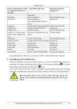
Fault Message on the Display

-

Fault message as text on the LCD.

-

Operating control light flashes red.

Display LCD

Possible Cause

Corrective Action

KLbasic/

KL24base

KLplus/

KL24plus

No display, no light

Power is disconnected

Check the power supply to the plant and 

controller

Check the microfuse F1 on the supply line

Check the position of the maintenance 

switch (position 1)

if the buffer is empty, a power failure will 

be indicated neither acoustically nor visually.

No display, light is green

Switch off the plant and turn it back on 

after 10 second.

No/weak display

Contrast is set 

incorrectly

Hold down ESC key and adjust contrast, 

using the arrow keys.

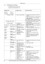
Set the clock

Set the clock

Internal clock/date not 

set

Make settings in the menu item Date and 

Time

Compress

Fault

**Malfunction*

*

Com. Fault 

Compressor is not 

working/will not power 

on

Check the main fuse F1

Check the compressor in manual mode

Valve 1

Fault

**Malfunction*

*

Valve 1

Valve does not operate

Blown fuse

Winding defective

Valve jammed due to 

obstruction

Cable break

Check the valve in manual mode 

Check the microwire fuse of the 

consumers F2

Check the valve for possible smoke 

residue

Unscrew the valve from the metal bar, 

check it for dirt, and remove dirt (see 

Maintenance Instructions in the 

Appendix).

Valve 2

Fault

**Malfunction*

*

Valve 2

Valve 3

Fault

**Malfunction*

*

Valve 3

Valve 4

Fault

**Malfunction*

*

Valve 4

-

**Malfunction*

*

UV module

UV module does not 

work

Check the UV module and the remaining 

lamp life

-

**Malfunction*

*

min fill level

Compressed air line 

leak between control 

and charging lifter, e.g., 

due to loose hose

Check hose for leaks

-

Warning

Backwater

Water level is too high in 

chamber 1

Compressed air line 

clogged, e.g. due to 

kinked hose

See Point 8.2

Check hose for kinks

-

Temperature 

max

Temperature sensor not 

plugged in 

Cabinet fan is not 

working

Filters dirty in the 

cabinet and the 

compressor 

Direct sunlight on the 

cabinet

Temperatures for 

Plug in temperature sensor on back of 

controller

Check the function of the cabinet fan

Check air filter in the cabinet

Shade location

Provide cool ventilation

Check air filter in the air compressor

Check air compressor in manual mode

Have maintenance company check set 

temperatures

KLARO GmbH

Original Operating Manual for KLARO Small Wastewater Treatment Plant V.15.07

33

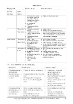
Display LCD

Possible Cause

Corrective Action

KLbasic/

KL24base

KLplus/

KL24plus

turning on the cooling 

fan and the maximum 

temperature that are 

entered in the Service 

menu are too high 

Air compressor 

defective

Temperature sensor 

defective

Replace temperature sensor 

-

**Malfunction*

*

Temp Sensor

Temperature sensor is 

missing

Temperature sensor is 

not fully plugged into the 

socket

Temperature sensor 

defective

Replace sensor

Ensure secure connection between 

controller and temperature sensor. Then 

power off controller for 10 sec. and switch 

it back on. Check whether a temp sensor 

fault message is displayed.

Power Failure

**Malfunction*

*

Power Failure

Power Failure

Plant switched off via 

maintenance switch

No voltage on the 

cabinet

FI fuse has blown

Wait for power to return

Switch plant on via maintenance switch 

Check supply to the switch cabinet

Locate cause for triggering the RCCB and 

correct it (possible cause: solenoid valve 

defective).

-

**Malfunction*

*

Modem

Batteries in the module 

are not yet fully charged

Modem has no mains 

voltage

No SIM card inserted in 

the modem

SIM card is not 

registered to the

network

Wait 5 minutes until batteries are fully 

charged

Connect modem to power

Insert SIM card in the modem

Wait until the card is registered. 

Otherwise relocate antenna so that 

reception is possible.

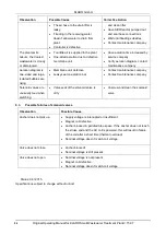
8.2.

Unusual Water Levels - Troubleshooting

Observation

Possible Cause

Corrective Action

The water level in the 
pre-treatment is 
unusually high, water 
level in the aeration  
is normal.

The lifter at valve 1 is not triggered.

The pumping time for lifter 1 is set too 
short.

The charging lifter is congested.

The air supply to the charging lifter is 
leaky.

Trigger valve 1 via manual 
operation and check the 
operation of the lifter. 

Have time for valve 1 increased 
by Service Company

Have pre-treatment pumped out 
and clean lifter

Have pre-treatment pumped out 
and seal hose connections

The water level in the 
pre-treatment and in 
the aeration basin is 
unusually high.

Plant is running in holiday mode.

Plant is constantly running in cycle 
pause.

Control settings are incorrect.

The drain lifter is congested.

Exit the holiday mode (see Point 
5.3.4)

Have the controller settings 
checked by service technician

Have SBR reactor pumped out 

KLARO GmbH

2

Original Operating Manual for KLARO Small Wastewater Treatment Plant V.15.07

IMPORTANT: 

This Operating Manual contains information about the plant, from installation 

to maintenance, and must therefore be read before commissioning of the 

plant!

All safety instructions must be observed!

The Operating Manual must be kept readily available during the operation of 

the plant!

Plant Specifications

For any questions in the course of the operation of the plant, the specifications of your plant should 
be noted as follows. With the help of this information, our staff will be able to help you more quickly 
in the event of a malfunction. The specifications can be found on the nameplate, which is located 
on the outside of the cabinet door for indoor cabinets, and inside the cabinet for outdoor cabinets.

Small Wastewater Treatment 

Plant

PT

Sludge storage

Buffer

SB-Reactor

Approval No.:

Process class:

Certified:

Cabinet:

Controller:

Compressor: 

Denomination:

Serial No.:

Article No.:

Additional module:

Article No.:

El. Connected load:

KLARO GmbH

Original Operating Manual for KLARO Small Wastewater Treatment Plant V.15.07

3

CONTENTS

Page

1.


About this Operating Manual

6


1.1.


Original Language of Documentation

6


1.2.


Completeness

6


1.3.


Liability

7


2.


Safety

7


2.1.


Explanation of Warnings and Prohibitions

7


2.2.


Hazard statements

8


2.3.


Warnings

9


2.4.


Exclusion for Use

10


3.


Warranty

10


4.


Function of the SBR Plant

10


4.1.


Plants for carbon elimination (process classes C)

11


4.2.


Systems with Additional Nitrogen Removal (Process Classes N and D)

13


4.3.


Systems with Additional Phosphate Elimination (Process Class +P)

13


4.4.


Systems with Additional Sanitation (Process Class +S)

13


5.


Control of the Small Wastewater Treatment Plant

13


5.1.


Connections to the KL-controls (230V option for solenoid valves)

16


5.2.


Connections to the KL24 controller(24V option for stepper motor valves)

16


5.3.


Operating the Controller

18


5.3.1.


Querying Operating Hours

18


5.3.2.


Manual Control of the Valves and the Cabinet Fan in "Manual Mode"

19


5.3.3.


Setting Date/Time

20


5.3.4.


Set Holiday Mode

20


5.3.5.


Query Malfunctions - Query Old Malfunctions

21


5.3.6.


Display Settings

21


5.3.7.


Service Menu and Action Code

21


5.4.


Changing the Fuses

22


5.5.


Operation of Power Failure Detector

22


6.


Additional functions of the Controllers KLplus/ KL24plus and KLbasic/KL24base

23


6.1.


Underload detection (KLplus/KL24plus)

23


6.1.1.


Mode of Operation

24


6.1.2.


Commissioning

24


6.1.3.


Switching Off the Level Measurement

25


6.1.4.


Safety and Fault Messages

25


6.2.


Optional Functions

26


6.2.1.


Connection of an external alarm device

26


6.2.2.


Connection of a contactor for switching the compressor

26


6.2.3.


Connection of a UV reactor

26


6.2.4.


Phosphate precipitation with metering pump

26


7.


Maintenance, Repair and Operation

28


7.1.


Sludge Evacuation

28


7.2.


Operating Instructions

29


8.


Fault Messages and Troubleshooting

31


8.1.


Fault Message on the Display

32


8.2.


Unusual Water Levels - Troubleshooting

33


KLARO GmbH

2

Original Operating Manual for KLARO Small Wastewater Treatment Plant V.15.07

IMPORTANT: 

This Operating Manual contains information about the plant, from installation 

to maintenance, and must therefore be read before commissioning of the 

plant!

All safety instructions must be observed!

The Operating Manual must be kept readily available during the operation of 

the plant!

Plant Specifications

For any questions in the course of the operation of the plant, the specifications of your plant should 
be noted as follows. With the help of this information, our staff will be able to help you more quickly 
in the event of a malfunction. The specifications can be found on the nameplate, which is located 
on the outside of the cabinet door for indoor cabinets, and inside the cabinet for outdoor cabinets.

Small Wastewater Treatment 

Plant

PT

Sludge storage

Buffer

SB-Reactor

Approval No.:

Process class:

Certified:

Cabinet:

Controller:

Compressor: 

Denomination:

Serial No.:

Article No.:

Additional module:

Article No.:

El. Connected load:

KLARO GmbH

Original Operating Manual for KLARO Small Wastewater Treatment Plant V.15.07

3

CONTENTS

Page

1.


About this Operating Manual

6


1.1.


Original Language of Documentation

6


1.2.


Completeness

6


1.3.


Liability

7


2.


Safety

7


2.1.


Explanation of Warnings and Prohibitions

7


2.2.


Hazard statements

8


2.3.


Warnings

9


2.4.


Exclusion for Use

10


3.


Warranty

10


4.


Function of the SBR Plant

10


4.1.


Plants for carbon elimination (process classes C)

11


4.2.


Systems with Additional Nitrogen Removal (Process Classes N and D)

13


4.3.


Systems with Additional Phosphate Elimination (Process Class +P)

13


4.4.


Systems with Additional Sanitation (Process Class +S)

13


5.


Control of the Small Wastewater Treatment Plant

13


5.1.


Connections to the KL-controls (230V option for solenoid valves)

16


5.2.


Connections to the KL24 controller(24V option for stepper motor valves)

16


5.3.


Operating the Controller

18


5.3.1.


Querying Operating Hours

18


5.3.2.


Manual Control of the Valves and the Cabinet Fan in "Manual Mode"

19


5.3.3.


Setting Date/Time

20


5.3.4.


Set Holiday Mode

20


5.3.5.


Query Malfunctions - Query Old Malfunctions

21


5.3.6.


Display Settings

21


5.3.7.


Service Menu and Action Code

21


5.4.


Changing the Fuses

22


5.5.


Operation of Power Failure Detector

22


6.


Additional functions of the Controllers KLplus/ KL24plus and KLbasic/KL24base

23


6.1.


Underload detection (KLplus/KL24plus)

23


6.1.1.


Mode of Operation

24


6.1.2.


Commissioning

24


6.1.3.


Switching Off the Level Measurement

25


6.1.4.


Safety and Fault Messages

25


6.2.


Optional Functions

26


6.2.1.


Connection of an external alarm device

26


6.2.2.


Connection of a contactor for switching the compressor

26


6.2.3.


Connection of a UV reactor

26


6.2.4.


Phosphate precipitation with metering pump

26


7.


Maintenance, Repair and Operation

28


7.1.


Sludge Evacuation

28


7.2.


Operating Instructions

29


8.


Fault Messages and Troubleshooting

31


8.1.


Fault Message on the Display

32


8.2.


Unusual Water Levels - Troubleshooting

33


33

Summary of Contents for LA-100

Page 1: ...ro d u c t s M ade in Germ a n y Operating manual for KLARO small wastewater treatment plants We provide clean water No mechanical parts in the wastewater No pumps in the wastewater No electrical part...

Page 2: ...questions in the course of the operation of the plant the specifications of your plant should be noted as follows With the help of this information our staff will be able to help you more quickly in t...

Page 3: ...ontroller 18 5 3 1 Querying Operating Hours 18 5 3 2 Manual Control of the Valves and the Cabinet Fan in Manual Mode 19 5 3 3 Setting Date Time 20 5 3 4 Set Holiday Mode 20 5 3 5 Query Malfunctions Qu...

Page 4: ...RO GmbH 2 Original Operating Manual for KLARO Small Wastewater Treatment Plant V 15 07 IMPORTANT This Operating Manual contains information about the plant from installation to maintenance and must th...

Page 5: ...6 1 1 Mode of Operation 24 6 1 2 Commissioning 24 6 1 3 Switching Off the Level Measurement 25 6 1 4 Safety and Fault Messages 25 6 2 Optional Functions 26 6 2 1 Connection of an external alarm devic...

Page 6: ...MoAnl 19 Factory Calibration Controller MoAnl 20 Submersible Pump for Additional Buffer Date of print 06 2015 KLARO GmbH 2 Original Operating Manual for KLARO Small Wastewater Treatment Plant V 15 07...

Page 7: ...rs KLplus KL24plus and KLbasic KL24base 23 6 1 Underload detection KLplus KL24plus 23 6 1 1 Mode of Operation 24 6 1 2 Commissioning 24 6 1 3 Switching Off the Level Measurement 25 6 1 4 Safety and Fa...

Page 8: ...s be left running except for maintenance purposes because proper wastewater treatment cannot be ensured otherwise KLARO GmbH 2 Original Operating Manual for KLARO Small Wastewater Treatment Plant V 15...

Page 9: ...al Mode 19 5 3 3 Setting Date Time 20 5 3 4 Set Holiday Mode 20 5 3 5 Query Malfunctions Query Old Malfunctions 21 5 3 6 Display Settings 21 5 3 7 Service Menu and Action Code 21 5 4 Changing the Fuse...

Page 10: ...system essentially consists of 2 stages A sludge storage with integrated pre buffer and an activated sludge stage in a closed sequencing batch reactor SBR The upstream sludge storage with integrated b...

Page 11: ...oliday Mode 20 5 3 5 Query Malfunctions Query Old Malfunctions 21 5 3 6 Display Settings 21 5 3 7 Service Menu and Action Code 21 5 4 Changing the Fuses 22 5 5 Operation of Power Failure Detector 22 6...

Page 12: ...o holiday mode The holiday mode is a greatly reduced operating mode of the plant during longer periods without wastewater inflow Figure 1 Membrane Tube Diffusor Figure 2 Membrane Plate Diffusor KLARO...

Page 13: ...07 3 CONTENTS Page 1 About this Operating Manual 6 1 1 Original Language of Documentation 6 1 2 Completeness 6 1 3 Liability 7 2 Safety 7 2 1 Explanation of Warnings and Prohibitions 7 2 2 Hazard stat...

Page 14: ...tion about the plant from installation to maintenance and must therefore be read before commissioning of the plant All safety instructions must be observed The Operating Manual must be kept readily av...

Page 15: ...6 1 1 Mode of Operation 24 6 1 2 Commissioning 24 6 1 3 Switching Off the Level Measurement 25 6 1 4 Safety and Fault Messages 25 6 2 Optional Functions 26 6 2 1 Connection of an external alarm devic...

Page 16: ...riginal Operating Manual for KLARO Small Wastewater Treatment Plant V 15 07 IMPORTANT This Operating Manual contains information about the plant from installation to maintenance and must therefore be...

Page 17: ...22 6 Additional functions of the Controllers KLplus KL24plus and KLbasic KL24base 23 6 1 Underload detection KLplus KL24plus 23 6 1 1 Mode of Operation 24 6 1 2 Commissioning 24 6 1 3 Switching Off t...

Page 18: ...be read before commissioning of the plant All safety instructions must be observed The Operating Manual must be kept readily available during the operation of the plant Plant Specifications For any q...

Page 19: ...e Valves and the Cabinet Fan in Manual Mode 19 5 3 3 Setting Date Time 20 5 3 4 Set Holiday Mode 20 5 3 5 Query Malfunctions Query Old Malfunctions 21 5 3 6 Display Settings 21 5 3 7 Service Menu and...

Page 20: ...19 12 2015 Mo 20 15 56 20 15 Mo 19 12 15 KLARO GmbH 2 Original Operating Manual for KLARO Small Wastewater Treatment Plant V 15 07 IMPORTANT This Operating Manual contains information about the plant...

Page 21: ...e KL controls 230V option for solenoid valves 16 5 2 Connections to the KL24 controller 24V option for stepper motor valves 16 5 3 Operating the Controller 18 5 3 1 Querying Operating Hours 18 5 3 2 M...

Page 22: ...rogram settings etc is saved However if no time and date is set no weekly operating hours of the units will be saved Future fault messages will be saved with an incorrect date KLARO GmbH 2 Original Op...

Page 23: ...astewater Treatment Plant 13 5 1 Connections to the KL controls 230V option for solenoid valves 16 5 2 Connections to the KL24 controller 24V option for stepper motor valves 16 5 3 Operating the Contr...

Page 24: ...ICE CODE INPUT press the key and enter the following code when prompted 9 9 9 9 Calibrate No Use the arrow keys to select CALIBRATE YES and confirm with the key and start the calibration Figure 11 Cha...

Page 25: ...Process Classes N and D 13 4 3 Systems with Additional Phosphate Elimination Process Class P 13 4 4 Systems with Additional Sanitation Process Class S 13 5 Control of the Small Wastewater Treatment Pl...

Page 26: ...chloride and ethylene oxide there is a hazard of explosion Consult the appropriate Material Safety Data Sheet before using phosphate precipitants Wear protective clothing when handling poly aluminium...

Page 27: ...he KL24 controller 24V option for stepper motor valves 16 5 3 Operating the Controller 18 5 3 1 Querying Operating Hours 18 5 3 2 Manual Control of the Valves and the Cabinet Fan in Manual Mode 19 5 3...

Page 28: ...o that the sludge storage space is sufficient for permanent full load operation and compliance with the operating and maintenance requirements for at least 12 months At a lower load this period is ext...

Page 29: ...gs and Prohibitions 7 2 2 Hazard statements 8 2 3 Warnings 9 2 4 Exclusion for Use 10 3 Warranty 10 4 Function of the SBR Plant 10 4 1 Plants for carbon elimination process classes C 11 4 2 Systems wi...

Page 30: ...o the workers in sewers and treatment plant Garbage bin Pipe cleaners Corrode pipes and seals poison the District collection centres KLARO GmbH 2 Original Operating Manual for KLARO Small Wastewater T...

Page 31: ...Manual Control of the Valves and the Cabinet Fan in Manual Mode 19 5 3 3 Setting Date Time 20 5 3 4 Set Holiday Mode 20 5 3 5 Query Malfunctions Query Old Malfunctions 21 5 3 6 Display Settings 21 5 3...

Page 32: ...on of the cabinet fan Check air filter in the cabinet Shade location Provide cool ventilation Check air filter in the air compressor Check air compressor in manual mode Have maintenance company check...

Page 33: ...Wastewater Treatment Plant 13 5 1 Connections to the KL controls 230V option for solenoid valves 16 5 2 Connections to the KL24 controller 24V option for stepper motor valves 16 5 3 Operating the Con...

Page 34: ...anual contains information about the plant from installation to maintenance and must therefore be read before commissioning of the plant All safety instructions must be observed The Operating Manual m...

Page 35: ...2 Operating Instructions 29 8 Fault Messages and Troubleshooting 31 8 1 Fault Message on the Display 32 8 2 Unusual Water Levels Troubleshooting 33 KLARO GmbH Original Operating Manual for KLARO Smal...

Page 36: ...astewater Treatment Plant PT Sludge storage Buffer SB Reactor Approval No Process class Certified Cabinet Controller Compressor Denomination Serial No Article No Additional module Article No El Connec...

Page 37: ...epair and Operation 28 7 1 Sludge Evacuation 28 7 2 Operating Instructions 29 8 Fault Messages and Troubleshooting 31 8 1 Fault Message on the Display 32 8 2 Unusual Water Levels Troubleshooting 33 KL...

Page 38: ...eatment Plant PT Sludge storage Buffer SB Reactor Approval No Process class Certified Cabinet Controller Compressor Denomination Serial No Article No Additional module Article No El Connected load KLA...

Page 39: ...ntenance Repair and Operation 28 7 1 Sludge Evacuation 28 7 2 Operating Instructions 29 8 Fault Messages and Troubleshooting 31 8 1 Fault Message on the Display 32 8 2 Unusual Water Levels Troubleshoo...

Page 40: ...fer SB Reactor Approval No Process class Certified Cabinet Controller Compressor Denomination Serial No Article No Additional module Article No El Connected load KLARO GmbH 2 Original Operating Manual...

Page 41: ...ce Repair and Operation 28 7 1 Sludge Evacuation 28 7 2 Operating Instructions 29 8 Fault Messages and Troubleshooting 31 8 1 Fault Message on the Display 32 8 2 Unusual Water Levels Troubleshooting 3...

Page 42: ...Treatment Plant PT Sludge storage Buffer SB Reactor Approval No Process class Certified Cabinet Controller Compressor Denomination Serial No Article No Additional module Article No El Connected load...

Page 43: ...Repair and Operation 28 7 1 Sludge Evacuation 28 7 2 Operating Instructions 29 8 Fault Messages and Troubleshooting 31 8 1 Fault Message on the Display 32 8 2 Unusual Water Levels Troubleshooting 33 K...

Page 44: ...Wastewater Treatment Plant PT Sludge storage Buffer SB Reactor Approval No Process class Certified Cabinet Controller Compressor Denomination Serial No Article No Additional module Article No El Conne...

Page 45: ...l of the Valves and the Cabinet Fan in Manual Mode 19 5 3 3 Setting Date Time 20 5 3 4 Set Holiday Mode 20 5 3 5 Query Malfunctions Query Old Malfunctions 21 5 3 6 Display Settings 21 5 3 7 Service Me...

Page 46: ...quickly in the event of a malfunction The specifications can be found on the nameplate which is located on the outside of the cabinet door for indoor cabinets and inside the cabinet for outdoor cabin...

Page 47: ...of the Valves and the Cabinet Fan in Manual Mode 19 5 3 3 Setting Date Time 20 5 3 4 Set Holiday Mode 20 5 3 5 Query Malfunctions Query Old Malfunctions 21 5 3 6 Display Settings 21 5 3 7 Service Men...

Page 48: ...u more quickly in the event of a malfunction The specifications can be found on the nameplate which is located on the outside of the cabinet door for indoor cabinets and inside the cabinet for outdoor...

Page 49: ...s KL24plus and KLbasic KL24base 23 6 1 Underload detection KLplus KL24plus 23 6 1 1 Mode of Operation 24 6 1 2 Commissioning 24 6 1 3 Switching Off the Level Measurement 25 6 1 4 Safety and Fault Mess...

Page 50: ...quickly in the event of a malfunction The specifications can be found on the nameplate which is located on the outside of the cabinet door for indoor cabinets and inside the cabinet for outdoor cabin...

Page 51: ...ility 7 2 Safety 7 2 1 Explanation of Warnings and Prohibitions 7 2 2 Hazard statements 8 2 3 Warnings 9 2 4 Exclusion for Use 10 3 Warranty 10 4 Function of the SBR Plant 10 4 1 Plants for carbon eli...

Page 52: ...el besch digt ist muss es durch den Hersteller seine autorisierten H ndler oder qualifizierte Personen ersetzt werden um eine Gefahr zu vermeiden 6 Stellen Sie keine Gegenst nde auf das elektrische Ka...

Page 53: ...Setzen Sie Dichtung A11 in den Geh usedeckel und Dichtung B12 am Pumpengeh use ein dann befestigen Sie das Vordergeh use 10 mit den Sechskantschrauben 9 Ziehen Sie die Sechskantschrauben 9 nach und n...

Page 54: ...g B 1 2 3 13 Kolben 1 2 3 18 Federteller 1 2 3 19 Feder 1 2 3 7 Kolbenk rper Feder Federteller Fett Teflonschicht KLARO GmbH 2 Original Operating Manual for KLARO Small Wastewater Treatment Plant V 15...

Page 55: ...1 About this Operating Manual 6 1 1 Original Language of Documentation 6 1 2 Completeness 6 1 3 Liability 7 2 Safety 7 2 1 Explanation of Warnings and Prohibitions 7 2 2 Hazard statements 8 2 3 Warnin...

Page 56: ...ater Treatment Plant V 15 07 IMPORTANT This Operating Manual contains information about the plant from installation to maintenance and must therefore be read before commissioning of the plant All safe...

Page 57: ...4 4 Systems with Additional Sanitation Process Class S 13 5 Control of the Small Wastewater Treatment Plant 13 5 1 Connections to the KL controls 230V option for solenoid valves 16 5 2 Connections to...

Page 58: ...nt All safety instructions must be observed The Operating Manual must be kept readily available during the operation of the plant Plant Specifications For any questions in the course of the operation...

Page 59: ...3 7 Service Menu and Action Code 21 5 4 Changing the Fuses 22 5 5 Operation of Power Failure Detector 22 6 Additional functions of the Controllers KLplus KL24plus and KLbasic KL24base 23 6 1 Underload...

Page 60: ...ant All safety instructions must be observed The Operating Manual must be kept readily available during the operation of the plant Plant Specifications For any questions in the course of the operation...

Page 61: ...4 Changing the Fuses 22 5 5 Operation of Power Failure Detector 22 6 Additional functions of the Controllers KLplus KL24plus and KLbasic KL24base 23 6 1 Underload detection KLplus KL24plus 23 6 1 1 Mo...

Page 62: ...he plant All safety instructions must be observed The Operating Manual must be kept readily available during the operation of the plant Plant Specifications For any questions in the course of the oper...

Page 63: ...1 5 3 7 Service Menu and Action Code 21 5 4 Changing the Fuses 22 5 5 Operation of Power Failure Detector 22 6 Additional functions of the Controllers KLplus KL24plus and KLbasic KL24base 23 6 1 Under...

Page 64: ...ily available during the operation of the plant Plant Specifications For any questions in the course of the operation of the plant the specifications of your plant should be noted as follows With the...

Page 65: ...5 5 Operation of Power Failure Detector 22 6 Additional functions of the Controllers KLplus KL24plus and KLbasic KL24base 23 6 1 Underload detection KLplus KL24plus 23 6 1 1 Mode of Operation 24 6 1 2...

Page 66: ...the specifications of your plant should be noted as follows With the help of this information our staff will be able to help you more quickly in the event of a malfunction The specifications can be fo...

Page 67: ...ying Operating Hours 18 5 3 2 Manual Control of the Valves and the Cabinet Fan in Manual Mode 19 5 3 3 Setting Date Time 20 5 3 4 Set Holiday Mode 20 5 3 5 Query Malfunctions Query Old Malfunctions 21...

Page 68: ...0615 part of the GRAF group KLARO GmbH Spitzwegstra e 63 95447 Bayreuth Telephone 49 0 921 16279 0 Fax 49 0 921 16279 100 E Mail info klaro eu More information at www klaro eu Technical hotline 49 0...

Reviews: