KLARO GmbH
Original Operating Manual for KLARO Small Wastewater Treatment Plant V.15.07
57
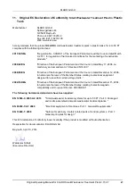
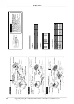
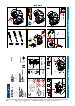
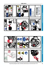
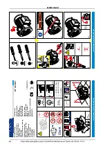
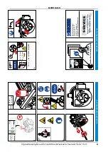
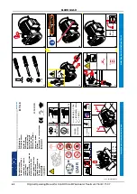
13.2. Rotary Vane Compressor Becker and Rietschle
Note:
The Becker rotary vane compressor we use are equipped with a pressure relief valve, which is factory set to
a maximum pressure of 0.5 bar.
With our plants, an operating pressure of <0.3 bar is common. If a pressure > 0.5 bar occurs in the plant
(e.g., in case of a kinked air hose), a portion of the air is released through the relief valve. The compressor is
thus protected from damage or excessive wear.
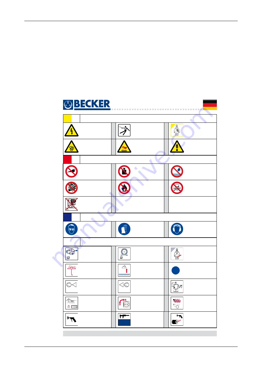
www.becker-international.com
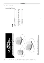
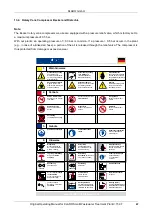
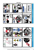
Warnhinweise
1.
Verbote
2.
Oil
Gebote
3.
Hinweise
4.
Schutzhandschuhe
tragen
Gehörschutz aufsetzen
Info über Schallpegel
z.B. 85 dB(A)
Schutzbrille aufsetzen
AIR
$,5
max.
800m
-
p
VACUUM
+
p
PRESSURE
L1
L2
L3
L1
L3
L2
50/60 Hz
=OFF
=ON
3000 h
i
+
L2 L1 L3
I
>
I
>
I
>
M
3
U1 V1 W1
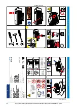
Gefährliche Spannung
nach
ANSI
Z535
(
A
merican
N
ational
S
tandards
I
nstitute)
Elektrofachkraft
gekennzeichnete Arbeits-
schritte dürfen nur durch
ausgebildete Elektrofach-
kraft erfolgen
Elektrische Spannung
kann tödlich sein.
Arbeiten an der Elektrik
nur durch ausgebildete
Elektrofachkraft
Automatischer Anlauf
möglich. Bei Service-
arbeiten das Gerät stets
stromlos schalten.
Heiße Oberflächen
führen zu Verbrennungen.
Vor Wartungarbeiten
Gerät abkühlen lassen.
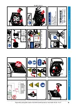
Achtung
Bei Nichtbeachtung kann
die Pumpe erheblich
beschädigt werden
Pumpe arbeitet ölfrei
Ansaugung von Ölnebel
vermeiden
Gekennzeichnete Stellen
nicht belasten
Explosive Stoffe
dürfen nicht gefördert
werden
Giftstoffe
dürfen nicht gefördert
werden
Brennstoffe
dürfen nicht gefördert
werden
Flüssigkeiten
dürfen nicht gefördert
werden
Aufstellung
unzulässige Einbaulage
Wirkprinzip
Drehschieberpumpe
Nur Luft ist als Förder-
medium zulässig
Wirkprinzip
Seitenkanalgebläse
Nur Luft ist als Förder-
medium zulässig
Wartungsarbeiten
gekennzeichnete Arbeits-
schritte regelmäßig
ausführen.
Sicherheitsventil
Ausführung
Vakuumpumpe
Ausführung
Verdichter
werksseitiges
Drehfeld
rechtsdrehend
als Voraussetzung für
Pumpenanschluß
Schaltintervall
nicht mehr als
10x
pro Stunde
Wartung (Filter)
je nach Staubanfall reinigen
verstopfte Patronen erneuern
alte Patrone entsorgen
gekennzeichnete
Bereiche mit Druckluft
ausblasen
Wartungsintervall
hier für Schiebermessung
nach 3.000 Betriebstunden.
(Mindestmaß beachten)
Motorschutzschalter
vorsehen
Lagerung / Aufstellung
Pumpe
vor Nässe
schützen
Aufstellung
Kenndaten
gelten bis zu
einer Höhe von 800m
weitere Informationen
(optionale Daten)
- Typenschilder
- Internet
KLARO GmbH
2
Original Operating Manual for KLARO Small Wastewater Treatment Plant V.15.07
IMPORTANT:
•
This Operating Manual contains information about the plant, from installation
to maintenance, and must therefore be read before commissioning of the
plant!
•
All safety instructions must be observed!
•
The Operating Manual must be kept readily available during the operation of
the plant!
Plant Specifications
For any questions in the course of the operation of the plant, the specifications of your plant should
be noted as follows. With the help of this information, our staff will be able to help you more quickly
in the event of a malfunction. The specifications can be found on the nameplate, which is located
on the outside of the cabinet door for indoor cabinets, and inside the cabinet for outdoor cabinets.
Small Wastewater Treatment
Plant
PT
Sludge storage
Buffer
SB-Reactor
Approval No.:
Process class:
Certified:
Cabinet:
Controller:
Compressor:
Denomination:
Serial No.:
Article No.:
Additional module:
Article No.:
El. Connected load:
KLARO GmbH
Original Operating Manual for KLARO Small Wastewater Treatment Plant V.15.07
3
CONTENTS
Page
1.
About this Operating Manual
6
1.1.
Original Language of Documentation
6
1.2.
Completeness
6
1.3.
Liability
7
2.
Safety
7
2.1.
Explanation of Warnings and Prohibitions
7
2.2.
Hazard statements
8
2.3.
Warnings
9
2.4.
Exclusion for Use
10
3.
Warranty
10
4.
Function of the SBR Plant
10
4.1.
Plants for carbon elimination (process classes C)
11
4.2.
Systems with Additional Nitrogen Removal (Process Classes N and D)
13
4.3.
Systems with Additional Phosphate Elimination (Process Class +P)
13
4.4.
Systems with Additional Sanitation (Process Class +S)
13
5.
Control of the Small Wastewater Treatment Plant
13
5.1.
Connections to the KL-controls (230V option for solenoid valves)
16
5.2.
Connections to the KL24 controller(24V option for stepper motor valves)
16
5.3.
Operating the Controller
18
5.3.1.
Querying Operating Hours
18
5.3.2.
Manual Control of the Valves and the Cabinet Fan in "Manual Mode"
19
5.3.3.
Setting Date/Time
20
5.3.4.
Set Holiday Mode
20
5.3.5.
Query Malfunctions - Query Old Malfunctions
21
5.3.6.
Display Settings
21
5.3.7.
Service Menu and Action Code
21
5.4.
Changing the Fuses
22
5.5.
Operation of Power Failure Detector
22
6.
Additional functions of the Controllers KLplus/ KL24plus and KLbasic/KL24base
23
6.1.
Underload detection (KLplus/KL24plus)
23
6.1.1.
Mode of Operation
24
6.1.2.
Commissioning
24
6.1.3.
Switching Off the Level Measurement
25
6.1.4.
Safety and Fault Messages
25
6.2.
Optional Functions
26
6.2.1.
Connection of an external alarm device
26
6.2.2.
Connection of a contactor for switching the compressor
26
6.2.3.
Connection of a UV reactor
26
6.2.4.
Phosphate precipitation with metering pump
26
7.
Maintenance, Repair and Operation
28
7.1.
Sludge Evacuation
28
7.2.
Operating Instructions
29
8.
Fault Messages and Troubleshooting
31
8.1.
Fault Message on the Display
32
8.2.
Unusual Water Levels - Troubleshooting
33
KLARO GmbH
2
Original Operating Manual for KLARO Small Wastewater Treatment Plant V.15.07
IMPORTANT:
•
This Operating Manual contains information about the plant, from installation
to maintenance, and must therefore be read before commissioning of the
plant!
•
All safety instructions must be observed!
•
The Operating Manual must be kept readily available during the operation of
the plant!
Plant Specifications
For any questions in the course of the operation of the plant, the specifications of your plant should
be noted as follows. With the help of this information, our staff will be able to help you more quickly
in the event of a malfunction. The specifications can be found on the nameplate, which is located
on the outside of the cabinet door for indoor cabinets, and inside the cabinet for outdoor cabinets.
Small Wastewater Treatment
Plant
PT
Sludge storage
Buffer
SB-Reactor
Approval No.:
Process class:
Certified:
Cabinet:
Controller:
Compressor:
Denomination:
Serial No.:
Article No.:
Additional module:
Article No.:
El. Connected load:
KLARO GmbH
Original Operating Manual for KLARO Small Wastewater Treatment Plant V.15.07
3
CONTENTS
Page
1.
About this Operating Manual
6
1.1.
Original Language of Documentation
6
1.2.
Completeness
6
1.3.
Liability
7
2.
Safety
7
2.1.
Explanation of Warnings and Prohibitions
7
2.2.
Hazard statements
8
2.3.
Warnings
9
2.4.
Exclusion for Use
10
3.
Warranty
10
4.
Function of the SBR Plant
10
4.1.
Plants for carbon elimination (process classes C)
11
4.2.
Systems with Additional Nitrogen Removal (Process Classes N and D)
13
4.3.
Systems with Additional Phosphate Elimination (Process Class +P)
13
4.4.
Systems with Additional Sanitation (Process Class +S)
13
5.
Control of the Small Wastewater Treatment Plant
13
5.1.
Connections to the KL-controls (230V option for solenoid valves)
16
5.2.
Connections to the KL24 controller(24V option for stepper motor valves)
16
5.3.
Operating the Controller
18
5.3.1.
Querying Operating Hours
18
5.3.2.
Manual Control of the Valves and the Cabinet Fan in "Manual Mode"
19
5.3.3.
Setting Date/Time
20
5.3.4.
Set Holiday Mode
20
5.3.5.
Query Malfunctions - Query Old Malfunctions
21
5.3.6.
Display Settings
21
5.3.7.
Service Menu and Action Code
21
5.4.
Changing the Fuses
22
5.5.
Operation of Power Failure Detector
22
6.
Additional functions of the Controllers KLplus/ KL24plus and KLbasic/KL24base
23
6.1.
Underload detection (KLplus/KL24plus)
23
6.1.1.
Mode of Operation
24
6.1.2.
Commissioning
24
6.1.3.
Switching Off the Level Measurement
25
6.1.4.
Safety and Fault Messages
25
6.2.
Optional Functions
26
6.2.1.
Connection of an external alarm device
26
6.2.2.
Connection of a contactor for switching the compressor
26
6.2.3.
Connection of a UV reactor
26
6.2.4.
Phosphate precipitation with metering pump
26
7.
Maintenance, Repair and Operation
28
7.1.
Sludge Evacuation
28
7.2.
Operating Instructions
29
8.
Fault Messages and Troubleshooting
31
8.1.
Fault Message on the Display
32
8.2.
Unusual Water Levels - Troubleshooting
33
57

