background image

Instruction 

Manual 

         page 

______________________________________________________________________________________________________________________ 


Instruction Manual 

for the mains driven electric-hydraulic universal unit,  
Serial-No. .......................... 
 

Index 

 
1  

Introduction 

2  

Labels 

3  

Warranty 

4  

Description of the electric-hydraulic universal unit 

4.1  

Description of the components 

4.2  

Brief description of the important features of the unit 

5  

Remarks in respect of the determined use 

5.1


Operation of the unit 

5.1.1


Use of the crimping dies 

5.1.2


Use of the cutting dies 

5.1.3


Use of the punch adapter 

5.2  

Explanation of the application range 

5.3  

Mounting instructions 

5.4  

Service and Maintenance instructions  

5.5  

Storage and transport of the crimping unit. 

6 Troubleshooting 

Putting out of operation/waste disposal 

8 Technical 

data 


Symbols


Safety warnings 
Please do not disregard these instructions in order to 
avoid human injuries and environmental damages. 


Operational warnings 
Please do not disregard them to avoid damaging the 
pump unit. 


1.   Introduction


Before starting to use the tool please read the 
instruction manual carefully. 

 
Use this tool exclusively for its determined use. 
 
Mounting and assembly of connecting material with the help of this 
tool must only be performed by specially trained personnel. The 
minimum age is 16 years. 
 
This instruction manual has to be carried along during the entire life 
span of that tool. 
 
The operator has 
-  to guaranty the availability of the instruction manual for the user and 
-  to make sure, that the user has read and understood the instruction 

manual. 


2.   Labels


On the labels fixed on the housing of the tool you’ll find the type 
specification, name of the manufacturer and the company logo. On the 
opposite side of the housing you’ll find a label with technical data. The 
serial number is on the hydraulic cylinder between the housing and the 
head. On the head you’ll find a warning against crimping and cutting 
hazards. 
 

3.   Warranty


If correct operation is guaranteed our warranty is 12 months from the 
time of delivery. 
 

4.   Description of the electric-hydraulic universal unit


4.1. Description of the components


The electric-hydraulic universal unit is a hand held tool and consists of 
the following components:  


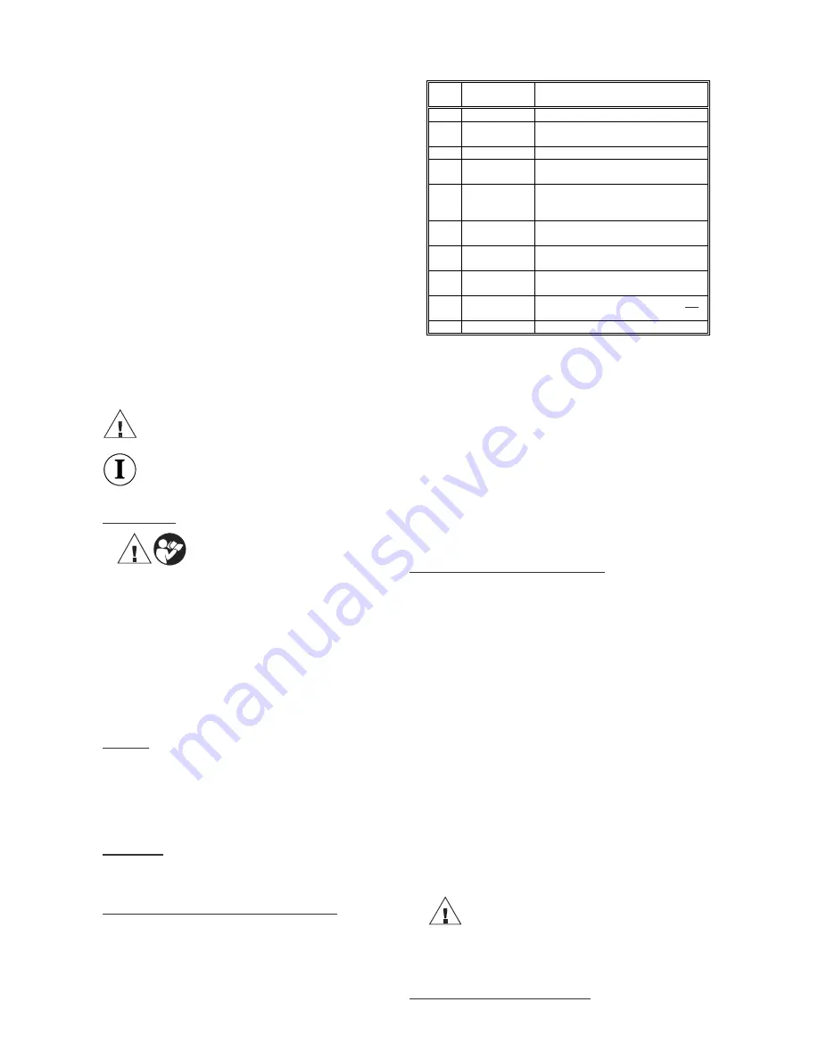
Table 1 (see Picture 1 page 2) 

Pos.-
No. 

Description Function 

Trigger 

switch to start working cycle 

Retract button 

button to retract the piston in case of 
error or emergency 

Latch 

device to open/close the head 

Adapter 

Provides the use of different common 
crimping dies 

Housing 

ergonomically formed plastic housing 
for perfect handling with a detachable 
lid 

Locking pin 

Adapter and cutting blades must be 
locked with this pin prior to operation 

7 Bending 

protection 

Protection device for mains cord to 
prohibit conductor breakage 

Ring 

Loop to secure the tool and/or for 
assembly purposes 

9 Removable 

hand guard 

guard to protect the operating hand, not 
for transportation 

10 

Dies (example)  interchangeable 22 style crimping dies 


4.2. Brief description of the important features of the unit


-


The hydraulic unit incorporates an automatic retraction which returns 
the piston into its starting position when the required maximum force 
is reached. 

-


The unit is equipped with a special brake which stops the forward 
motion of the piston when the trigger (Pos.-No. 1) is released. 

-


The unit is equipped with a double piston pump which is characterised 
by a rapid approach of the crimping/cutting dies (Pos.-No. 4+10, chart 
2) towards the connector and a slow working motion. 

-


The head can be smoothly turned by 360° around the longitudinal axis 
in order to gain better access to tight corners and other difficult 
working areas. 

-


Compatability to all common crimping dies (60kN) by using special 
adapters 

-


Use of special dies and adapters including customer specific die 
designs. 


5.   Remarks in respect of the determined use 

 
Before starting any work on electrical appliances it must be safeguarded 
that there are no live parts in the immediate assembly area of the user. Is 
this not possible special precaution measures

1

 for working near live parts 

must be provided. 
 

5.1. Operation of the unit


First the mains voltage must checked whether it matches with the 
required tool voltage and then the mains plug must be plugged into the 
socket. Since the unit is dooble insulated you can also use a not 
grounded socket to connect the tool the te mains supply. 
 
Then you have to select the right adapter for the type of dies (Pos.-No. 4, 
10) you intend to use respectively the cutting blades. Afterwards the 
head has to be opened by unhooking the latch (Pos.-No. 3 & Picture 2 
Pos. A).  
 
The adapters will be inserted into the universal head. Please follow 
pictures 8-13 vicariously for all adapters and dies. Please make sure that 
the locking pins (Pos.-No. 11) are always fully engaged. 
 
After having completely closed the universal head the crimping/cutting 
procedure is initiated by actuating the trigger (Pos.-No. 1 & Picture 2 
Pos. C). The working cycle is defined by the closing motion of the 
dies/blades.  
 

Attention 
The crimping process can be interrupted at any moment 
by releasing the trigger. 

 
In case of error or emergency the dies/blades can be returned into the 
starting position by actuating the retract button (Pos.-No. 2 & Picture 2 
Pos. B). 


1


See EN 50110-1 

Summary of Contents for Multi

Page 1: ...JCS H DOKU BED_KL HYDR HE12532 doc HE 12532 02 08 Anzahl der Seiten 14 Bedienungsanleitung Instruction Manual NK60UNV110 Serialnummer ...

Page 2: ...te 2 _____________________________________________________________________________________________________________________ Bild Picture 1 3 8 10 5 6 1 2 9 7 4 UA22 UC40 UCD UA6P Bild Picture 3 6 Bild Picture 2 Bild Picture 7 ...

Page 3: ..._____________________________ Bild Picture 8 13 8 9 10 11 12 13 Tabelle Chart 1 Pressen Crimping Adapter Einsätze Dies First crimp Side a First crimp Side b Crimping direction First crimp Crimping direction Side a Crimping direction Side b Bild Picture 14 UA18 18 er Serie DIN 48083 T1 UA22 UA5 5 er Serie 22 er Serie ...

Page 4: ...l cutting blades Profil Schneideinsatz blade Profil Schneideinsatz blade UCD3575 Auf Anfrage UCD3515 Auf Anfrage Auf Anfrage UCD3215 UCACSR UC40 UC26 ACSR DIN 48204 40 mm NYY NAYY Cu Al 26 mm NYY NAYY Cu Al 40 mm UCD3515 35x15 EN 50035 G 32 EN 50022 35x7 5 M6 UCM6 M8 UCM8 M10 UCM10 UCUNC14 3 8 UCUNC38 UCM10 UA6P 60kN 16UNF Tragschiene top hat rail EN 50022 35x7 5 Tragschiene top hat rail ähnlich s...

Page 5: ...m Fehler bzw Notfall 3 Klappriegel zum Öffnen des Kopfes 4 Adapter Ermöglichen den Einsatz unterschied lichster marktüblicher Einsätze 5 Gehäuse Ergonomisch geformtes Kunststoff gehäuse 6 Verriegelungs stift Adapter und Schneideinsätze müssen mit dem Stift verriegelt werden 7 Knickschutz Vermeidung von zu engen Biegeradien des Netzkabels 8 Ring Öse zum Sichern des Werkzeuge und oder für die Montag...

Page 6: ...m Schneiden von Gewindestangen muß darauf geachtet werden daß die Zuführung gerade ist d h daß rechtwinklig zum Schneid einsatz geschnitten wird Die Gewindestangenschneideinsätze von müssen vor Arbeitsbeginn von Spänen gesäubert werden 2 Siehe Bild 4 Montagehinweis für Kabelschuhe und Verbinder Beim Schneiden von Gewindestangen sollte der Vorgang bis zur Endlage der Schneid einsätze fortgesetzt we...

Page 7: ...nen b Das Gerät erreicht den Enddruck nicht Preß Schneidvorgang unterbrechen Rückstelltaste Pos Nr 2 gedrückt halten und gleichzeitig Bedienungsschalter ca 10 sec Dauerbetätigen Wird der Fehler dadurch nicht behoben muß das Gerät ins Werk eingeschickt werden 7 Außerbetriebnahme Entsorgung Die Entsorgung der einzelnen Komponenten des Aggregates muß getrennt erfolgen Dabei muß zuerst das Öl abgelass...

Page 8: ...gonomically formed plastic housing for perfect handling with a detachable lid 6 Locking pin Adapter and cutting blades must be locked with this pin prior to operation 7 Bending protection Protection device for mains cord to prohibit conductor breakage 8 Ring Loop to secure the tool and or for assembly purposes 9 Removable hand guard guard to protect the operating hand not for transportation 10 Die...

Page 9: ...the blades have reached their final position in order to provide clean cutting edges The DIN rail cutting dies are equipped with a sheet metal guide which facilitate a cut in a right angle When the cut is completed the retraction is provided by actuating the retract button Pos No 2 once 3 See picture 4 page 2 5 1 2 Use of the punch adapter The advance penetration of the punch into the die must be ...

Page 10: ...the operating switch continuously and simultaneously for about 10 sec Is the malfunction not be eliminated by this attempt the tool has to be returned to the manufacturer 7 Putting out of operation waste disposal The disposal of the various components of the tool has to be treated separately First you have to dispose of the oil at special delivery points Attention Hydraulic oils represent a danger...

Page 11: ... at POLEN UKRAINE RB Brexim S A Mr Marynin 7a 05 825 Grodzisk Mazowiecki Poland 0048 22 7344380 0048 22 7344381 rboffice brexim pl PORTUGAL Palissy Galvani Electricidade S A Ms Anna Pereira Rua Serpa Pinto 15 A B 1200 433 Lisboa Portugal 00351 21 3223400 00351 21 3223410 ana pereira palissygalvani pt SLOWENIEN Isaria d o o Ms Zorz Proizvdnja in trgovina Cece 2a 1420 Trbovlje Slovenia 00386 356 318...

Page 12: ... Eagle Hydraulic Equipment Maintenance Co Ltd Mr Song Junling RM A 2809 The Third Building No 1 Shuanguang Rd West Beijing 100028 China 86 10 64924396 86 10 58220595 service bjbsn com KOREA Taehyung Hydraulic Tool Mr Kim 140 5 Gamjeun Dong Sasang Gu Busan 17 060 Korea 0082 51 3171507 0082 51 3171507 thhyd hanmail net SCHWEDEN AB Lindströms Elverkstad Mr Anders Bennarsten Propellervägen 7 SE 39241 ...

Page 13: ...ch Vu Ngoc Trang 157 159 Xuan Hong Street Ward 12 Tan Binh District Ho Chi Minh City Vietnam 0084 8 8117454 0084 8 8116338 sales huuhong com vn TAIWAN Po Charng Co Ltd Mr Vincent Chen No 166 Sung Sin Road Sun Yi Dist Taipei 110 Taiwan 0084 886227631623 0084 886227667492 vincent cn msa hinet net JAPAN Osaka Hydraulics Mr Ryoji Furuya 10 32 Egasaki cho Tsurumi ku Yokohama 30 0002 Japan 0081 45 57038...

Page 14: ...ument EN 60745 1 EN 60745 2 8 EN 12100 Teil 1 2 EN 294 EN 349 EN 60204 1 EN 28662 1 EN 50081 1 EN 55014 2 EN 60529 enligt bestãmmelserna i direktiverna 98 37 EG 89 336 EG 73 23 EG FIN CE 08 Todistus slandardinmukaisuudesta Asiasta vastaavana todistamme täten että tämä tuote on seuraavien standardien ja standardoimisasiakirjojen vaatimusten mukainen EN 60745 1 EN 60745 2 8 EN 12100 Teil 1 2 EN 294 ...

Reviews: