background image

Klein + Hummel 

Operating Manual O 810 / O 870 

English 

28

Safety and Warnings


In addition to specific warnings throughout this document, please observe these additional general instructions. 
The term “loudspeaker” includes the case when the electronics of an active loudspeaker is installed into a Remote 
Electronics Kit, or when it is still located in the back of the cabinet. 


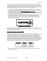
This symbol means that a high voltage is to found nearby. Take appropriate precautions to avoid electric 
shocks. 


This symbol means that hot parts of the product may be found nearby. Take appropriate precautions to 
avoid burns. 

 
General 


Keep these instructions in a safe place for future reference. 


Failure to follow the safety and warning instructions contained in this document voids the warranty. 


This product should be used for the intention for which it was designed and as described in this document. 

 
Environment 


Ensure that the room in which you use this product is wired in accordance with the local electrical code and 
checked by a qualified inspector. 


A correctly earthed mains power connection should always be used. 


If access to the interior electronics is required, disconnect it from the mains power and allow electrical energy 
storage devices, such as capacitors and transformers, to discharge. 


Other electronic products may generate sufficient heat to require ventilation. 


Do not block or cover heatsinks, fans, or vents. 


Unless otherwise stated, this product is designed to be used indoors only. 


Do not expose this product to water, any other liquids, moisture, or naked flames. 


Do not install this product into hot, humid, or excessively dusty locations, or into direct sunlight. 


Avoid installing this product into locations where it will experience externally generated vibrations or heat 
(e.g. radiators). 


If the product is moved from a cold environment into a warm one (such as from a vehicle into a building), it is 
possible that condensation will form. Please allow the product sufficient time for acclimatization to room 
temperature before using. 


Wherever an amplifier is located, a free flow of air should be maintained by leaving a gap of at least 5 cm 
(2”) around it. A flush mounted cabinet with the electronics panel still installed should be well-ventilated to 
avoid heat build-up and possible risk of fire. 

 
Use 


The equipment should be mounted by a suitably qualified professional in accordance with local, national, and 
international regulations and standards. 


Falling equipment can damage itself, people, and other objects, so do not place this unit on any unstable 
platform, cart, trolley, stand, table, or mounting hardware. 


Do not use accessories and options with this product that are not approved by Klein + Hummel. 


Mounting hardware must be attached to the appropriate hardware and attachment points rated and 
intended for such use. 


Ensure that the operating voltage of this product matches that of the local mains voltage. 


Use the power cable that came with this product as this has been manufactured to international safety 
standards. If it has been damaged obtain a similarly certified and specified mains power cable. 


This product should be unplugged from the mains power and the signal sources if is not to be used for an 
extended period of time, or during lightening storms. 


The power switch on this product should be set to off before applying mains power via the mains power 
cable. 


Some parts of this product, particularly power amplifier components, can become hot to the touch. Do not 
touch these parts until they have cooled down. 


Never touch the loudspeaker’s drivers. 


Loudspeakers are often capable of producing a sound pressure level in excess of 85 dB. This may cause 
permanent hearing damage so user caution is recommended. Noise exposure is a function of SPL and time, so 
observe local regulations when listening at high levels for a long time. Hearing protection may be required. 


Summary of Contents for 0 810

Page 1: ...Operating Manual O 810 O 870 Part Number 526393 Version 02 Date 21 Nov 2008 Language English Fran aise Deutsch Espa ol O 810 O 870 Active Subwoofer with 7 1 High Definition Bass Management...

Page 2: ......
Page 3: ...trol 21 Cleaning 22 Technical Specifications 23 Acoustical Measurements 24 Accessories and Options 26 Safety and Warnings 28 Maintenance and Servicing 29 Guarantee 29 Recycling 29 EC Declaration of Co...

Page 4: ...fer Wahl 60 System Blockdiagramme 61 Elektronikfeld 62 Crossover 62 Mains Sektion 63 Analog Input Karte 63 Optionale Digital Input Karte DIM 4 64 Output Karte 66 Filterkarte 66 Verst rkermodul e 68 Tr...

Page 5: ...rjeta de filtros 94 M dulos amplificadores 96 Bocinas y respuesta ac stica 96 Gabinete 96 Montaje remoto de los circuitos electr nicos 97 Uso del sistema 97 Controles de sonido 102 Calibrando los cont...

Page 6: ...this operating manual review the safety and warnings section towards the back of this book Note that imperial dimensions are approximate Package Contents The shipping carton contains This operating m...

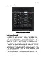
Page 7: ...DIM 4 fitted The 7 1 High Definition Bass Manager is organized in to an Input Card analog or digital Output Card Filter Card Amplifier Module s and Mains Card There is 1 power amplifier and driver in...

Page 8: ...subwoofer is 0 dB unless some attenuation has been applied by the volume control function The LFE channel is processed independently see the Filter Card LFE Mode section for details In addition to th...

Page 9: ...s power circuit board and move the switch towards the large black capacitor Close the electronics panel and reattach the mains power and signal cables Power up the subwoofer apply 12V to the remote co...

Page 10: ...n the table below With the exception of the LFE channel the seven main channels may be used for any broadband signal however the output channel ordering will depend on the input signal order Input Sta...

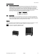
Page 11: ...NC connectors protrude from the cabinet s back panel The circuit board will be damaged if the cabinet is placed vertically on a flat hard surface with the driver s facing upwards only recommended when...

Page 12: ...ng the phase control see Calibrating Phase section The Subwoofer Gain Subwoofer Phase Parametric Equalizer and Low Cut controls are described in the Acoustical Controls section below LFE channel repro...

Page 13: ...surround sound processor or DVD Blue ray disk player usually the Subwoofer output Additionally this mode is useful for detecting higher frequency signals up to 300 Hz in the LFE channel that should ot...

Page 14: ...output and the cabinet volume can be seen in the Specifications section below Klein Hummel subwoofers are designed to have a flat pass band magnitude response in anechoic conditions when all the acous...

Page 15: ...e ensure that the correct mains voltage is indicated on the electronics panel 220 240V or 100 120 V and that the mains power switch is off Next connect the input signal cables analog or digital as app...

Page 16: ...to design an effective flush mounting wall If the loudspeakers and subwoofers must be covered use a thin open weave cloth Two layers of very thin material will improve opacity The 80 Hz crossover is l...

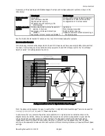
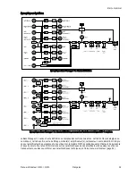
Page 17: ...nection Examples In the following interconnection diagrams O 300 and O 810 have been shown as examples Other products from the Klein Hummel range can be substituted for example O 410 and O 870 Please...

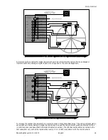
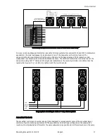
Page 18: ...he main loudspeakers Digital connections to the 7 1 High Definition Bass Manager To increase the number of subwoofers in a system to make a Plane Wave Bass Array the subwoofers should be set up as sho...

Page 19: ...Calibration section The LFE channel should be connected to all of the subwoofers using XLR Y cables and the signal level adjusted at the source by 9 5 dB or 0 5 dB so that the reproduction level at 0...

Page 20: ...ualizer using the bypass switch The Subwoofer Phase controls consist of a 0 180 switch and 0 45 90 135 switch This applies a very short delay 45 at 80 Hz 1 56 ms to the subwoofer output and gives a po...

Page 21: ...easurement system to the one of the following target responses In studio applications the response of each loudspeaker at the listening position should be flat In movie applications the response of ea...

Page 22: ...r setting Finally check the result with the other loudspeakers in the system by connecting different loudspeakers to the left output socket It is possible that the same setting is not valid for all lo...

Page 23: ...igh levels with all the main loudspeakers muted subwoofer is soloed to find the source of rattles in the listening room Using subwoofer mute and bass management together gives some useful additional f...

Page 24: ...the volume of individual output channels for trimming of the main loudspeaker levels and subwoofer level System volume control is also possible as are some additional functions Channel muting and solo...

Page 25: ...Input sensitivity 8 and 6 dBu CMRR 60 dB 15 kHz Interchannel isolation 1 kHz level matching 95 dB 0 1 dB Volume control range resolution 118 dB 0 25 dB Dynamic range THD N 119 dB A better than 0 001...

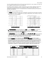
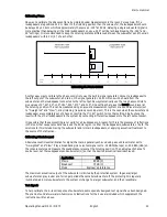
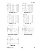
Page 26: ...ments conducted in anechoic conditions at 1 m Color versions of these graphs can be found on the appropriate product page of the klein hummel com web site O 870 with O 410 free field response O 870 wi...

Page 27: ...nglish 25 O 810 with O 110 free field response O 810 with O 300 free field response O 810 with O 110 group delay O 810 with O 300 group delay O 810 harmonic distortion noise at 95 dB SPL O 810 harmoni...

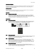
Page 28: ...l the volume of the entire monitoring system The 10 dB LFE gain can also be switched on and off remotely A cable must be purchased separately see Remote Cables RC nn below Button Left Right Function B...

Page 29: ...installed The connections are as follows note Bass 2 is not used when there is only one driver in the cabinet Drivers Speakon Pins Bass 1 1 Bass 2 2 SC nn Subwoofer Cable Cables of length 2 5 10 15 20...

Page 30: ...a warm one such as from a vehicle into a building it is possible that condensation will form Please allow the product sufficient time for acclimatization to room temperature before using Wherever an a...

Page 31: ...nel is opened If the main fuse blows the product should be checked by a Klein Hummel certified service engineer Guarantee This product comes with a guarantee a copy of which is enclosed with this prod...

Page 32: ...esigned to provide reasonable protection against harmful interference in a residential installation This equipment generates uses and can radiate radio frequency energy and if not installed and used i...

Page 33: ...vant de lire le reste de ce manuel utilisateur commencez pas la section S curit et Avertissements en fin de manuel Contenu du carton Vous trouverez dans le carton d emballage Ce manuel utilisateur Le...

Page 34: ...ons suivantes carte d entr e analogique ou num rique carte de sortie carte de filtrage module s amplificateur s carte secteur Le mod le O 810 int gre un seul amplificateur de puissance et un seul boom...

Page 35: ...ns de reproduction sonore fr quemment rencontr es en milieu domestique Les signaux des canaux principaux restent un gain unitaire lorsqu ils traversent le caisson de graves soit 0 dB de gain moins qu...

Page 36: ...ez simple de fa on taler dans le temps la demande de courant lors de l allumage Notez que ce connecteur allume teint l lectronique du caisson de graves de fa on globale ce n est pas un simple circuit...

Page 37: ...es liaisons sym triques entre le caisson de graves et les enceintes principales Source RCA Loudspeaker XLR M 1 3 2 Unbalanced RCA to Balanced XLR Connections C ble signal pour sources asym triques De...

Page 38: ...impl mentation de ce standard Le r glage du volume du syst me est encore possible en utilisant le connecteur de contr le distance SRC 1 ou 2 ou RS 232 pour agir sur les blocs de contr le VOL de la sor...

Page 39: ...e la sortie Sum est toujours analogique les caissons de graves situ s apr s le premier dans une daisy chain ne doivent pas avoir de carte d entr e num rique optionnelle DIM 4 install e Carte de Filtra...

Page 40: ...ement LFE sur la carte d entr e analogique ou entr e 2 subframe B sur la carte d entr e num rique La reproduction du canal LFE n est pas affect e par le r glage du s lecteur de Bass Management Voici l...

Page 41: ...c ble CAT ne doit pas transporter de signal IP Klein Hummel propose deux t l commandes r f rence SRC 1 et SRC 2 livr s avec des c bles CAT 5 de haute qualit en diff rentes longueurs termin s par des...

Page 42: ...D s qu un caisson de graves est install dans un environnement d coute r el sa courbe de r ponse change il faut donc lui appliquer des corrections pour r tablir une courbe de r ponse lin aire Il est do...

Page 43: ...reste allum le caisson fonctionne alors correctement Si l indicateur ne s allume pas v rifiez si la prise secteur est aliment e Dans le sens inverse teindre le caisson de graves coupe imm diatement le...

Page 44: ...issons de graves Un caisson de graves suffit dans le cas o la place ou le budget sont limit s Toutefois v rifiez que le niveau acoustique de sortie du caisson est adapt celui des enceintes principales...

Page 45: ...de plusieurs caissons de graves reportez vous la section Contr le de Volume Exemples d interconnexion Dans les sch mas d interconnexion suivants nous avons pris comme exemple des enceintes O 300 et de...

Page 46: ...r glages de phase diff rents Connexion simultan e de signaux 5 1 et 2 0 au Bass Manager 7 1 canaux haute d finition Un exemple d interconnexion de signaux num riques est illustr ci dessous Veuillez n...

Page 47: ...ssons de graves afin de constituer un Plane Wave Bass Array Vous pouvez adopter une installation en colonne 4 voies pour de gros syst mes utilisant par exemple une enceinte O 410 et un caisson O 870 c...

Page 48: ...param trique Le potentiom tre Parametric Equalizer correspond une bande d galiseur param trique offrant un r glage de gain 4 12 dB de frequency 20 120 Hz et Q 1 8 afin de compenser les non lin arit s...

Page 49: ...10 r m me si ce n est pas toujours le cas Niveau signal d entr e dBu 0 0 775 V 4 1 23 V R glage de niveau d entr e dB 1 5 R glage de niveau de sortie dB SPL 100 100 Distance d coute m att nuation dB 5...

Page 50: ...225 en activant les r glages 180 et 45 Il est recommand de maintenir une diff rence de distance d coute entre le caisson et les enceintes principales inf rieure 2 m tres Calibration du potentiom tre P...

Page 51: ...apport par le circuit de bass manager soit de 0 dB pour tous les canaux gain unitaire Lorsque la source ne dispose pas d un r glage de volume vous pouvez y pallier en r glant le volume sonore dans le...

Page 52: ...du commerce car selon son c blage interne des dommages sont possibles Une fois le protocole USB converti en RS 232 un adaptateur RS 232 vers CAT 5 est n cessaire pour brancher le caisson de graves vo...

Page 53: ...u caisson de graves Vous pouvez galement r gler le niveau global du syst me et acc der quelques autres fonctions Le Mute et le Solo de canaux sont galement accessibles si une carte DIM 4 est install e...

Page 54: ...13 k Sensibilit d entr e 8 et 6 dBu Taux de r jection de mode commun CMRR 60 dB 15 kHz Diaphonie 1 kHz pr cision de niveau entre canaux 95 dB 0 1 dB ventail de r glage de volume r solution 118 dB par...

Page 55: ...tiques effectu es en chambre sourde relev es une distance de 1 m Vous retrouverez ces courbes en couleurs sur la page produit correspondante du site Web www klein hummel com R ponse en champ libre O 8...

Page 56: ...e 54 R ponse en champ libre O 810 avec O 110 R ponse en champ libre O 810 avec O 300 Temps de propagation de groupe O 810 avec O 110 Temps de propagation de groupe O 810 avec O 300 THD Bruit O 810 95...

Page 57: ...nt Contr les distance SRC 1 T l commande Subwoofer Cette petite t l commande permet de bypasser le circuit de bass management et de contr ler le niveau d coute de tout le syst me Vous pouvez galement...

Page 58: ...re le caisson puisque le connecteur une fois en place est orient vers le bas Voici le brochage du connecteur Remarque Boomer 2 n est pas utilis si le caisson de graves ne contient qu un seul transduct...

Page 59: ...d un radiateur par exemple Si vous faites passer ce produit d un environnement froid un environnement chaud il est possible que de la condensation apparaisse l int rieur du coffret Avant de brancher...

Page 60: ...l Seul cas o l lectronique peut tre ouverte par une autre personne qu un technicien agr Klein Hummel la mise en place d options installables par l utilisateur comme d crit dans le manuel utilisateur d...

Page 61: ...able contre les interf rences nuisibles dans le cadre d une installation r sidentielle Cet appareil g n re utilise et peut rayonner de l nergie dans le domaine des fr quences radio s il n est pas inst...

Page 62: ...Jahre begeistert einsetzen werden Bevor Sie das restliche Bedienungshandbuch lesen sollten Sie den Abschnitt mit den Sicherheits und Warnhinweisen am Ende dieses Handbuchs durchgehen Hinweis Englische...

Page 63: ...liertem DIM 4 Der 7 1 High Definition Bass Manager besteht aus einer Input Karte analog oder digital Output Karte Filter Karte sowie Amplifier Modul en und Mains Karte Der O 810 ist mit 1 Endstufe und...

Page 64: ...woofer durchlaufenden Hauptkan le betr gt 0 dB sofern keine Bed mpfung mit dem Volume Regler angewandt wurde Der LFE Kanal wird unabh ngig bearbeitet weitere Details im Abschnitt Filterkarte LFE Modus...

Page 65: ...m Geh use oder am Remote Electronics Kit durch L sen d 6 Inbusschrauben Suchen Sie den gro en Schalter auf der Netzstromplatine und bewegen Sie den Schalter in Richtung des gro en schwarzen Kondensato...

Page 66: ...usskonverter Signale verarbeiten k nnen 4 x XLR und 4 x BNC Anschl sse garantieren gute Interkonnektivit tsoptionen obwohl immer nur einer der Sockel einer Eingangsstufe verwendet werden sollte Die DI...

Page 67: ...ieren das direkt vor den DACs platziert ist Man kann die Zeitverz gerung auf alle acht Eingangskan le gleicherma en anwenden um verz gerte Videosignale zu kompensieren Diese Einrichtung ist nicht zum...

Page 68: ...internen Microcontrollers und schnell bei Aktivierung des Schutzsystems Im letzteren Fall sollten Sie das Eingangssignal zur ckdrehen einen gr eren Subwoofer verwenden oder das System durch weitere Su...

Page 69: ...Hz vom Subwoofer wiedergegeben ber 80 Hz wird der LFE Kanal zu den linken und rechten Ausg ngen geleitet Um die akustische Verst rkung um 6 dB bei der Wiedergabe eines Signals ber zwei Lautsprechersy...

Page 70: ...Treiber Die Verst rker arbeiten mit Class D Technologie um Verlustleistung gering zu halten und werden im gebr ckten Modus betrieben um Verzerrungen zu minimieren Dennoch wird um das Elektronikfeld h...

Page 71: ...t eine Linie die senkrecht zur Vorderseite des Subwoofers verl uft entlang der das Mikrofon zur Feinabstimmung des Subwoofer Crossovers w hrend der Entwicklung aufgestellt wurde Bei den Subwoofern der...

Page 72: ...Right 30 22 5 Left Surround 110 10 ein Array links Right Surround 110 10 ein Array rechts F r 2 kanaliges Stereo sollte man 30 verwenden Momentan gibt es keine internationalen Standards f r die 6 1 o...

Page 73: ...LFE SUB ONLY 120 gesetzt sollte man den Subwoofer Abstand auf weniger als 70 cm 2 5 verringern Die akustische Verst rkung bei wechselseitiger Kopplung ist in der folgenden Tabelle aufgef hrt Anzahl an...

Page 74: ...ch f r 1 0 2 0 3 1 0 5 0 5 1 6 0 6 1 und 7 1 Theater Signale verwendbar ist Zudem gibt es noch eine weniger offensichtliche aber sehr praktische Konfiguration Man kann ein 5 1 Signal wie im Diagramm u...

Page 75: ...tigt Digitalanschl sse zum 7 1 High Definition Bass Manager Um die Anzahl an Subwoofern in einem System zu erh hen und ein Plane Wave Bass Array zu bilden sollten die Subwoofer wie in der Abbildung u...

Page 76: ...B oder 0 5 dB angepasst werden damit der Wiedergabepegel bei 0 oder 10 dB konsistent zu den Hauptkan len ist Left Right Center LFE Montage eines gro en Systems zur Bildung eines 4 Weg S ulensystems Ak...

Page 77: ...0 Hz 1 56 ms auf den Subwoofer Ausgang an und bewirkt eine positionelle Aufl sung von 0 54 m 1 9 Diese Regler richten den Subwoofer akustisch neu zu den Hauptlautsprechern aus wenn sie in unterschiedl...

Page 78: ...der folgenden Zielfrequenzg nge In Studioanwendungen sollte der Frequenzgang jedes Lautsprechers an der Abh rposition linear verlaufen In Filmanwendungen sollte der Frequenzgang jedes Lautsprechers e...

Page 79: ...Ergebnis mit den anderen Lautsprechern im System indem Sie unterschiedliche Lautsprecher an die linke Ausgangsbuchse anschlie en M glicherweise gilt die gleiche Einstellung nicht f r alle Lautspreche...

Page 80: ...sch spielen Sie bei stummgeschalteten Hauptlautsprechern Subwoofer auf Solo besonders basshaltiges Material mit hohen Pegeln ab um die Quelle von Rasselger uschen im Abh rraum zu finden Durch den geme...

Page 81: ...g Man kann mit RS 232 Anweisungen die Pegel einzelner Ausgangskan le steuern um die Pegel der Hauptlautsprecher oder Subwoofer abzustimmen Eine Systempegelsteuerung sowie einige Zusatzfunktionen sind...

Page 82: ...tunterdr ckung 60 dB 15 kHz Isolation zwischen Kan len 1 kHz Pegel bereinstimmung 95 dB 0 1 dB Pegelsteuerungsbereich Aufl sung 118 dB 0 25 dB Dynamikbereich Klirrfaktor Rauschen 119 dB A besser als 0...

Page 83: ...er reflexionsarmen Bedingungen mit 1 m Abstand durchgef hrt Farbversionen dieser Diagramme finden Sie auf der entsprechenden Produktseite der klein hummel com Website O 870 mit O 410 Freifeld Frequenz...

Page 84: ...870 Deutsch 82 O 810 mit O 110 Freifeld Frequenzgang O 810 mit O 300 Freifeld Frequenzgang O 810 mit O 110 Gruppendelay O 810 mit O 300 Gruppendelay O 810 Klirrfaktor Rauschen bei 95 dB SPL O 810 Klir...

Page 85: ...l sst sich ebenfalls ferngesteuert ein und ausschalten Das Kabel ist separat erh ltlich siehe Fernbedienungskabel RC nn weiter unten Taste Left Right Funktion Bass Management LFE Gain Taste gel st LED...

Page 86: ...g ist wie folgt Hinweis Wenn das Geh use nur einen Treiber enth lt wird Bass 2 nicht benutzt Treiber Speakon Pole Bass 1 1 Bass 2 2 SC nn Subwooferkabel Kabel der L ngen 2 5 10 15 20 25 und 30 m 6 15...

Page 87: ...er offenem Feuer aus Installieren Sie dieses Produkt nicht an hei en feuchten oder exzessiv staubigen Orten oder im direkten Sonnenlicht Installieren Sie dieses Produkt m glichst nicht an Orten an den...

Page 88: ...m Anwender nicht gewartet werden Reparaturen sollten nur von zertifizierten Klein Hummel Wartungstechnikern durchgef hrt werden Das Risiko beim Einbau von Sonderzubeh r und Zubeh r tr gt der Anwender...

Page 89: ...unterliegt folgenden zwei Bedingungen Dieses Ger t darf keine st renden Interferenzen erzeugen und dieses Ger t muss empfangene Interferenzen verkraften k nnen einschlie lich Interferenzen die eventu...

Page 90: ...lea con cuidado las instrucciones de seguridad hacia el final de este manual de operaci n Recuerde que las medidas en sistema ingl s son aproximadas Contenido La caja contiene lo siguiente El manual d...

Page 91: ...ion Bass Manager est organizado en una tarjeta de entrada anal gica o digital una tarjeta de salida una tarjeta de filtros uno o m s m dulos amplificadores y un m dulo de alimentaci n El O 810 contien...

Page 92: ...se aplique cierto grado de atenuaci n por medio de la funci n de control del volumen El canal LFE se procesa de manera independiente para mayor informaci n vea la secci n correspondiente a la Tarjeta...

Page 93: ...era sido encendido y apagada usando el interruptor principal Para activar el circuito remoto de 12 V Apague el subwoofer y desconecte los cables de se al y alimentaci n Abra el panel de circuitos elec...

Page 94: ...mo AES EBU AES3id 2001 y S P DIF con un convertidor adecuado 4 conectores XLR y 4 conectores BNC garantizan una buena interconectividad aunque s lo una de las conexiones de la etapa de entrada deber u...

Page 95: ...strador de bajos El intervalo de tiempo de un cuadro depende de la frecuencia de las im genes 50 Hz 40 ms o 60 Hz 33 ms La tasa de muestreo se detecta autom ticamente y afecta el m ximo retraso posibl...

Page 96: ...ajos de los canales posteriores mientras que otros no El uso de este control evita tener que desconectar las conexiones XLR de estos canales La reproducci n del canal LFE no se ve afectada por el func...

Page 97: ...e superiores de las bocinas izquierda y derecha en el canal LFE que de otra manera deber an evitarse 2 LFE SUB ONLY 80 El canal LFE se reproduce hasta 80 Hz nicamente en el subwoofer Esto viene de una...

Page 98: ...storsi n debida a la intermodulaci n y el ruido el rendimiento es tan bueno como en los dise os clase AB Bocinas y respuesta ac stica Las bocinas son las mejores que hay en el mercado para este tipo d...

Page 99: ...una ventilaci n adecuada Aunque no se da en una ventilaci n insuficiente har que la protecci n del amplificador se active prematuramente limitando as el m ximo nivel de salida del sistema Uso del sis...

Page 100: ...mpensar las diferencias en el tiempo de propagaci n Esto se puede hacer ya sea con un controlador digital externo Pro C 28 colocado en la ruta de la se al antes de la bocina o acoplado a la entrada di...

Page 101: ...os peque os y de tres a cuatro para cuartos m s grandes Los subwoofers deber n colocarse a lo largo de la pared del frente con un espacio adecuado entre ellos vea el p rrafo anterior para generar una...

Page 102: ...l como se muestra en el siguiente diagrama Asimismo los dos canales posteriores sin usar pueden conectarse a un sistema 2 0 separado y usar el subwoofer para dar mayor amplitud de bajos a un segundo p...

Page 103: ...ubwoofers deber n estar calibrados para su respuesta en el lugar vea las secciones de Controles de sonido y Calibraci n El canal LFE deber estar conectado nicamente al primer subwoofer de manera que e...

Page 104: ...ofers hay tres reas que requieren de especial atenci n la respuesta del subwoofer en el lugar la fase entre el subwoofer y las bocinas y el nivel ac stico absoluto en relaci n con las bocinas principa...

Page 105: ...vel de salida para un voltaje de entrada dado es 2 dB y 114 dB SPL at 1m y el menos sensible es 12 dB y 100 dB SPL at 1m Nivel de presi n de sonido dB SPL de la bocina a 1m cuando la se al de entrada...

Page 106: ...alores como un buen punto de inicio para un ajuste posterior Controles de sonido Ubicaci n de la bocina Nivel Low Cut Param trico En una esquina 8 dB 4 dB Cerca de o empotrado en un muro s lido 4 dB 2...

Page 107: ...dos de tiempo m s largos que los subwoofers peque os Si la luz del sistema de protecci n se ilumina regularmente a ada m s subwoofers al sistema o cambie a un subwoofer m s grande y cal brelos de nuev...

Page 108: ...ber n cruzarse es decir TX se conectar a RX y viceversa Adaptador RS 232 D Sub a CAT 5 Si el equipo de control tiene un conector USB entonces ser necesario un Adaptador USB a RS 232 No se recomienda u...

Page 109: ...ara ajustar los niveles de las bocinas principales y del subwoofer Tambi n es posible controlar el volumen del sistema al igual que algunas otras funciones adicionales Es posible silenciar los canales...

Page 110: ...tradas y salidas anal gicas Canales de entrada salida 7 1 7 Sum Impedancia el ctricamente balanceada XLR 13 k Sensibilidad de entrada 8 y 6 dBu CMRR 60 dB 15 kHz Aislamiento entre canales 1 kHz iguala...

Page 111: ...condiciones anecoicas a 1 m Las versiones en color de estos gr ficos se encuentran disponibles en la p gina web del producto en www klein hummel com Respuesta de frecuencia del O 870 en campo libre co...

Page 112: ...810 en campo libre con O 110 Respuesta de frecuencia del O 810 en campo libre con O 300 Demora de grupo del O 810 con O 110 Demora de grupo del O 810 con O 300 Distorsi n arm nica del O 810 ruido con...

Page 113: ...onitoreo El control de ganancia LFE de 10 dB tambi n puede activarse y desactivarse de forma remota El cable remoto RC nn se vende por separado Bot n Izquierdo Derecho Funci n Administrador de bajos G...

Page 114: ...o en que se instalan Las conexiones son las siguientes recuerde Bass 2 no se usa cuando s lo hay una bocina en el gabinete Bocinas Pins Speakon Bass 1 1 Bass 2 2 SC nn Cable para subwoofer Cables con...

Page 115: ...cta del sol Evite instalar este producto en locaciones en las que experimente calor o vibraciones generadas desde el exterior p ej cerca de radiadores Si este producto se traslada de un ambiente fr o...

Page 116: ...opciones y accesorios se incluyen a riesgo del usuario Los productos podr n limpiarse usando una tela no abrasiva ligeramente humedecida en agua Desconecte el cable de alimentaci n al momento de limpi...

Page 117: ...lamento de la FCC y con la norma RSS 210 de Industry Canada Su operaci n est sujeta a las siguientes condiciones Este equipo no deber causar interferencias da inas y Este equipo deber aceptar cualquie...

Page 118: ...uct or service names may be trademarks or service marks of other organizations Klein Hummel reserve the right to change product specifications without notice Exceptions and omissions excluded K H Vert...

Reviews: