4-8
CHAPTER 4 Maintenance and Troubleshooting
Series 5000 V2 Sonar System Operations and Maintenance Manual
P/N 11214512, Rev. 04
4.6
Installing the Towfish Electronics
To install the towfish
electronics:
1.
Slide the electronics gently
and carefully into the
pressure bottle, aligning the
alignment pin with the
notch in the pressure
housing.
2.
Locate the bulkhead
connectors on the
electronics housing end
cap. These connectors are
shown in Figure 4-10.
3.
Reconnect the cables to the
bulkhead connectors on the
electronics housing end
cap. The altimeter cable is
marked with colored shrink
tubing as shown in
Figure 4-11. Connect this
cable to the ALT connector
only.
CAUTION
Do not connect the altimeter cable to one of the transmit
transducer bulkhead connectors (TX-STBD or TX-PORT). Doing so may
damage the altimeter transducer when the side scan transmitters are
operating. Connect the altimeter cable to the ALT bulkhead connector only.
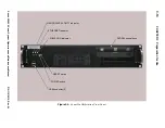
Figure 4-10:
Electronics Housing End Cap
Bulkhead Connectors
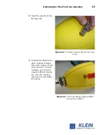
Figure 4-11:
Altimeter Cable Identified with
Colored Shrink Tubing
Altimeter
connection
Summary of Contents for 5000 V2 Series
Page 24: ......
Page 48: ......
Page 62: ......
Page 73: ...A 3 Figure A 1 Cable Length vs Towfish Depth Graph 1...
Page 75: ...A 5 Figure A 3 Cable Length vs Towfish Depth Graph 3...
Page 77: ...A 7 Figure A 5 Cable Length vs Towfish Depth Graph 5...
Page 78: ......
Page 82: ......
Page 88: ......
Page 92: ......
Page 95: ...E 3...
Page 97: ...E 5...
Page 99: ...E 7...
Page 101: ...E 9...
Page 103: ...E 11...
Page 105: ...E 13...
Page 107: ...E 15...
Page 109: ...E 17...
Page 111: ...E 19...


