5-4
CHAPTER 5 Technical Description
Series 5000 V2 Sonar System Operations and Maintenance Manual
P/N 11214512, Rev. 04
Multiplexer board.
The Multiplexer board digitizes the signals from each of
the transducer sub-array channels along with the signals from the sensors,
encodes the data, and transmits a high baud rate digital data stream to the TPU
by way of the tow cable. The Multiplexer board also receives the trigger signal
and command messages which instruct the Transmitter board to fire the arrays
and configure aspects of towfish operation. The Multiplexer board also acts as
a motherboard for the other boards providing the connections and distributing
power.
In addition, the Multiplexer board performs the following functions:
• Receives the 200 VDC and telemetry from the TPU and separates out the
telemetry from the 200 VDC.
• Routes the 200 VDC to the power supply, and then receives the converted
±12 VDC.
• Routes the 200 VDC to the Transmitter boards.
• Generates ±5 VDC, +3.3 VDC, and +28 VDC.
• Generates the time varied gain (TVG) curves for the received sonar signals
from the transducers.
• Multiplexes all the data channels and transmits the telemetry to the TPU.
• Provides cable uplink and downlink interface.
A full duplex hybrid allows data transmission up the cable while
simultaneously receiving the FSK trigger signals and power. The downlink
signals are input to FSK demodulators, and the baseband outputs are routed to
the Transmitter board, indicating when to fire the main array, and to a micro
controller that handles towfish configuration.
Compass board.
The compass board provides heading, pitch and roll.
5.1.2 Transducer Arrays
The two transducer arrays are each composed of 12 piezoelectric ceramic
sub-arrays that operate as both transmit and receive elements. Each set of
12 sub-arrays is arranged into a continuous line array spanning an overall aperture
of 1.2 meters. When the bathymetry option is present, 3 additional receive arrays
are included that feed the additional channels of the receiver boards.
Summary of Contents for 5000 V2 Series
Page 24: ......
Page 48: ......
Page 62: ......
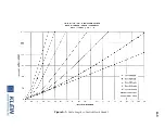
Page 73: ...A 3 Figure A 1 Cable Length vs Towfish Depth Graph 1...
Page 75: ...A 5 Figure A 3 Cable Length vs Towfish Depth Graph 3...
Page 77: ...A 7 Figure A 5 Cable Length vs Towfish Depth Graph 5...
Page 78: ......
Page 82: ......
Page 88: ......
Page 92: ......
Page 95: ...E 3...
Page 97: ...E 5...
Page 99: ...E 7...
Page 101: ...E 9...
Page 103: ...E 11...
Page 105: ...E 13...
Page 107: ...E 15...
Page 109: ...E 17...
Page 111: ...E 19...


