TJXTREME
Installation and Operation Manual
PG 27/36
REV: A (5/8/2020)
9.5.
Install Horn & Compressor Sub-Assembly (TJ-101)
9.5.1.
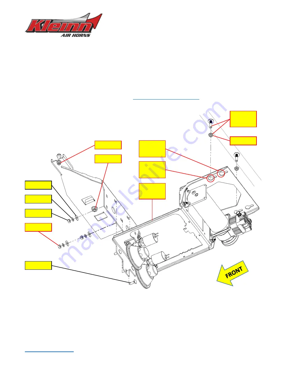
Lift Horn and Compressor Sub-Assembly into place, by first inserting Flange Nuts from earlier step
through Bracket key slot holes, then slide Bracket forward until contacting Tank Bracket.
NOTE A:
If installing kit solo and Carriage Bolts are pushing up out of floor, temporarily re-install Guide
Plate (TJ-001) in place over Bolt heads to keep them from lifting during this step.
NOTE B:
Rear axle vent hose may need to be temporarily moved if it interferes with Bracket install.
9.5.2.
While holding Sub-Assembly in place, install
, as shown below. It is
recommended to apply medium-strength Loctite to fasteners.
Figure 16
–
Installing Horn & Compressor Sub-Assembly, Exploded View (Air Tubing not Shown)
9.5.3.
Adjust Air Tank Bracket (TJ-201) laterally, to ensure Brackets align and provide at least 1/
4”
clearance
between all moving Brake Cables, Lines, Tubing, or Wiring.
Final torque fasteners, as shown above
.
CAUTION
: Do not over-torque Flange Nuts on Seat Bolts or Carriage Bolts; this may cause excessive
Bracket deformation or crushing of Rear Floor.
H10 (3)
H9 (3)
H11 (3)
H12 (3)
Previous
Step
75 in-lbs
50 in-lbs
TJ-101
Sub-Assy
12 ft-lbs
17 ft-lbs
Key Holes
for LJ
Key Holes
For TJ


