GMTRK4
Installation and Operation Manual
PG 37/42
REV: BETA (4/4/2020)
10.
On-Vehicle Electrical Installation
CAUTION:
Follow all recommended safety precautions for working on vehicle’s electrical system;
consult vehicle
owner’s manual for further instruction.
10.1.
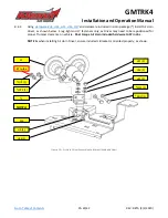
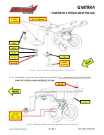
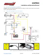
Relay and Fuse Diagram for Air Horn System
Figure 32
–
Suggested Ignition Relay Diagram for Air Horn System (Single 220 Horn Shown)
PRESSURE
SWITCH
(either wire
can go to
Relay or
Ignition)
AIR HORN
SOLENOID
(either wire
can be PWR
or GND)

