background image


190 

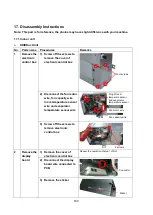
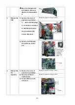
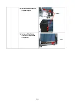
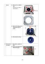
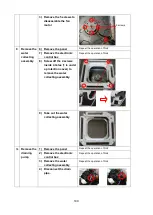
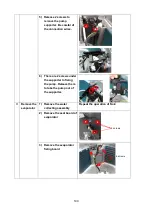
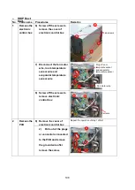
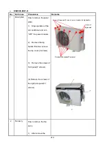
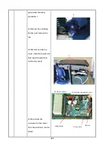
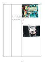
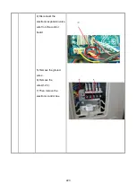
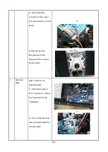
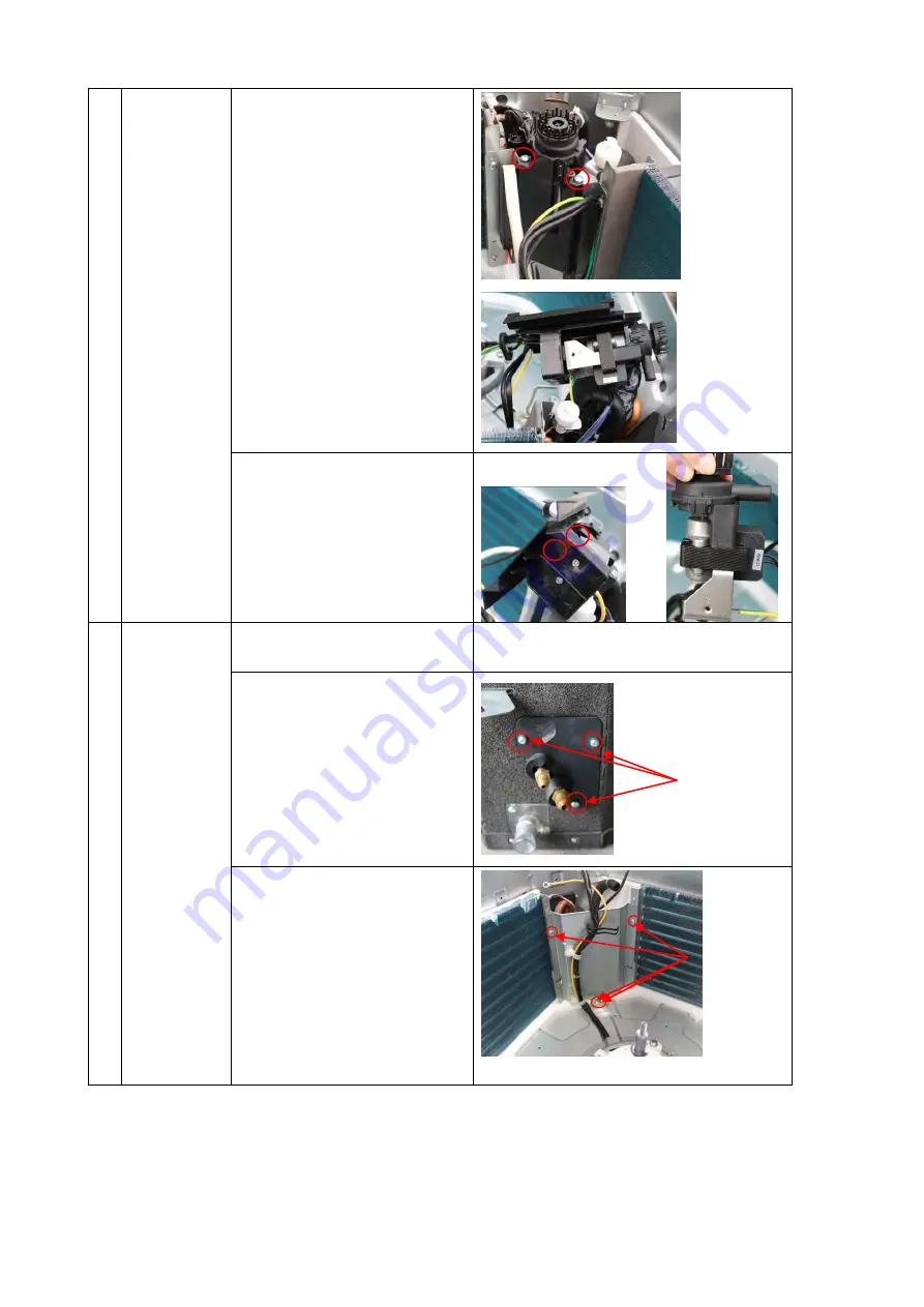
5)  Release 2 screws to 

remove the pump 
supporter. Be careful of 
the connection wires. 


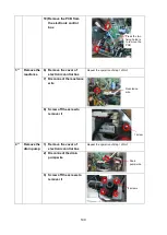
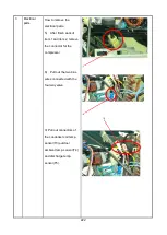
6)  There are 2 screws under 

the supporter to fixing 
the pump. Release them 
to take the pump out of 
the supporter. 


11 

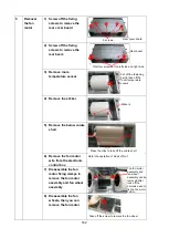
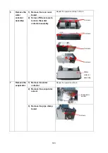
Remove the 
evaporator   

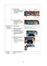
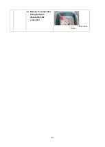
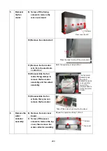
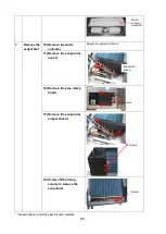
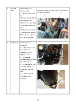
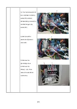
1)  Remove the water 

collecting assembly


Repeat the operation of No.9


2)  Remove the seal board of 

evaporator   


3)  Remove the evaporator 

fixing board 


3 screws 

4 screws 

Summary of Contents for KDIP012-H2

Page 1: ...cation of Power 12 Installation Details 13 Operation Characteristics 14 Electronic Function 15 Solar Panel 16 Troubleshooting 17 Disassembly Instructions WARNING Installation MUST conform with local building codes or in the absence of local codes with the National Electrical Code NFPA70 ANSI C1 1993 or current edition and Canadian Electrical Code Part1 CSA C 22 1 The information contained in the m...

Page 2: ...2 8 Electric Characteristics 96 9 Sound Level 97 9 1 Indoor unit 97 9 2 Outdoor unit 100 10 Accessories 101 11 The Specification of Power 103 13 Installation Details 106 13 1Location selection 106 13 2 Indoor unit installation 106 13 3 Outdoor unit installation 116 13 4 Refrigerant pipe installation 117 13 5 Drainage pipe installation 121 13 6 Vacuum Drying and Leakage Checking 124 13 7 Additional...

Page 3: ...16 Troubleshooting 138 16 1 Indoor Unit Error Display 139 16 2 Error Display on Two Way Communication Wired Controller 140 16 3 Outdoor unit error display 141 16 4 Diagnosis and Solution 145 16 5 Main parts check 172 17 Disassembly Instructions 180 17 1 Indoor unit 180 17 2 Outdoor unit 202 ...

Page 4: ...ct Sharp edges could cause injury be especially careful of the case edges and the fins on the condenser and evaporator For installation always contact the dealer or an authorized service center Do not install the product on a defective installation stand Be sure the installation area does not deteriorate with age If the base collapses the air conditioner could fall with it causing property damage ...

Page 5: ...repair of product Low refrigerant levels may cause failure of product Install the drain hose to ensure that water is drained away properly A bad connection may cause water leakage Keep level even when installing the product It can avoid vibration of water leakage Do not install the product where the noise or hot air from the outdoor unit could damage the neighborhoods It may cause a problem for yo...

Page 6: ...al injury Replace the all batteries in the remote control with new ones of the same type Do not mix old and new batteries or different types of batteries There is risk of fire or explosion Do not recharge or disassemble the batteries Do not dispose of batteries in a fire They may burn of explode If the liquid from the batteries gets onto your skin or clothes wash it well with clean water Do not us...

Page 7: ...Cassette 18K KTIR018 H2 KSIE018 H220 O A5 Duct KDIR18 H2 Floor Ceiling KUIR18 H2 A6 Duct KDIP018 H2 A6 Duct 24K KDIP24 H2 KSIE024 H220 O Cassette KTIR24 H2 A5 Duct KDIR24 H2 Floor Ceiling KUIR24 H2 Cassette 36K KTIR036 H2G1 KSIR036 H218 A5 Duct N A Floor Ceiling KFUF036 H2G1 A6 Duct KDIR036 H2G1 Cassette 48K KTIR048 H2G1 KSIR048 H218 A5 Duct N A Floor Ceiling KFUF048 H2G1 A6 Duct KDIR048 H2G1 HESP...

Page 8: ...5 2 2 Part names of Indoor Outdoor units Cassette Units ...

Page 9: ...6 KDIR Duct Units ...

Page 10: ...7 KDIP Duct Units ...

Page 11: ...9 Ceiling floor Units ...

Page 12: ...10 HESP DUCT Units ...

Page 13: ...d fresh air intake to outdoor Continually inhale the fresh air to improve the quality of the indoor air fulfills air quality more healthy and comfortable 2 3 1 3 Easy Maintenance Clean the filter Optional standard product without filter It is easy to draw out the filter from the indoor unit for cleaning even the filter is installed in rear side or bottom side Replace the motor or centrifugal fan R...

Page 14: ...troller or a central controller to realize remote on off control function or group control function 2 3 1 5 Built in Drain Pump Optional Built in drain pump can lift the water to 750mm upmost It s convenient to install drainage piping under most space condition Motor Blower Housing Ventilated Panel Remote on off ports Central control ports 750mm upmost ...

Page 15: ...ith a receiver in the E box Move out the display and fix it in other place even in the distance of 2m The unit will realized remoter control The wired controller and the display board can display the error code or production code when the chips detect some failure Display Wired Controller Standard Remote Controller Optional ...

Page 16: ... 3 Fire proof Controller Box Electrical control box adopts new design which can meet higher fire safety requirements 2 3 2 4 Fresh Air Fresh air intake function bring you fresh and comfortable air feeling 2 3 2 5 Wired Controller Optional Compared with infrared remote controller wired controller can be fixed on the wall and avoid mislaying It s mainly used for commercial zone and makes air conditi...

Page 17: ...o 750mm upmost It s convenient to install drainage piping under most space condition 2 3 2 7Terminals For Alarm Lamp and Long distance On off Controller Connection Are Standard Reserve terminals for the connection of alarm lamp and long distance on off controller more human control ...

Page 18: ...o airflow ways help to spread air comfortably throughout even a large room With these functions the whole room can be evenly air conditioned for both floor level and ceiling installation 2 3 4 4 Optional Drainage Pipe Connection Both right side and left side drainage holes are available to avoid the space limitation for drainage pipe installation Make you more convenient during installation 2 3 4 ...

Page 19: ...19 2 3 4 7 Outside Water Pump for Optional When Ceiling Installation ...

Page 20: ...nit 300mm 2 3 5 3 Constant air volume control For ordinary duct when the static pressure exceeds the expected range it is fairly difficult even for an experienced installer to calculate and adjust the air volume precisely With constant air volume control technology the duct will automatically adjusts to perfect static pressure and keep constant air volume 2 3 5 4 Flexible Air Intake Way Bottom sid...

Page 21: ...ve been detached heat exchanger and water receiver tray in behind can be seen very clearly Dust can be easily removed from the inside by vacuum 2 3 5 7 Fresh air intake function Optional Install one duct from the reserved fresh air intake to outdoor Continually inhale the fresh air to improve the quality of the indoor air fulfills air quality more healthy and comfortable Air intake from rear Stand...

Page 22: ...to improve the fresh air volume There are reserved ports for this motor on main PCB Standard for 3D inverter units and only optional for DC inverter 53 160 units 2 3 5 8 Drain pump Optional Built in drain pump can lift the water to 750mm upmost which widens the drainage piping range Max 750mm ...

Page 23: ...r spacious and large rooms like large stores and factories 2 3 6 2 Easy maintenance The unit can be opened from top or bottom The air outlet flange is isolated from either top panel or base panel which makes the maintenance much easier when connecting duct 2 3 6 3 Flexible Installation Different solutions for any shape room by using kinds of air distribution ducts L shaped area Areas far apart Y s...

Page 24: ...2 5 63 3 74 5 91 12 mm 700 210 635 570 65 493 35 119 595 200 80 740 350 120 143 95 150 in 27 56 8 27 25 22 44 2 56 19 41 1 38 4 69 23 43 7 87 3 15 29 13 13 78 4 72 5 63 3 74 5 91 18 mm 920 210 635 570 65 713 35 119 815 200 80 960 350 120 143 95 150 in 36 22 8 27 25 00 22 44 2 56 28 07 1 38 4 69 32 09 7 87 3 15 37 80 13 78 4 72 5 63 3 74 5 91 24 mm 920 270 635 570 65 713 35 179 815 260 20 960 350 1...

Page 25: ...as side Liquid side 4 install hanger Body Drain pipe 25 Fresh air intake 65 647 647 50 Drain hole for Service 545 570 260 68 42 157 126 44 Wiring connection port 75 E parts box 4 Screw hole for install panel 523 570 Wiring connection port ...

Page 26: ... A B A B Service hole for draining pump Fresh air intake 75 55 80 80 4 install hanger Gas side Liquid side E parts box 135 90 Panel Body 92 92 92 92 D D 92 92 D D D D 92 92 92 92 92 92 92 92 D D Capacity Btu h A B C D 24K mm 160 75 205 50 inch 6 30 2 95 8 07 1 97 36K mm 160 95 245 60 inch 6 30 3 74 9 65 2 36 48K mm 160 95 287 60 inch 6 30 3 74 11 30 2 36 ...

Page 27: ...ction port 204 94 Fresh air intake Drain discharge port Refrigerant pipe hole Hanging arm D Capacity Btu h A B C D 18K 24K mm 1068 675 235 983 inch 42 05 26 57 9 25 38 70 36K mm 1285 675 235 1200 inch 50 59 26 57 9 25 47 24 48K 60K mm 1650 675 235 1565 inch 64 96 26 57 9 25 61 61 ...

Page 28: ...6 5 5 27 8 2 0 5 4 30 8 7 5 1 6 36 2 20 0 3 1 5 8 3 5 4 4 24 mm 1100 249 774 700 140 926 50 175 1001 228 5 1140 598 80 150 130 155 inch 43 3 9 8 30 5 27 6 5 5 36 5 2 0 6 9 39 4 9 0 0 2 44 9 23 5 3 1 5 9 5 1 6 1 36 mm 1360 249 774 700 140 1186 50 175 1261 228 5 1400 598 80 150 130 155 inch 53 5 9 8 30 5 27 6 5 5 46 7 2 0 6 9 49 6 9 0 0 2 55 1 23 5 3 1 5 9 5 1 6 1 48 mm 1200 300 874 800 123 1044 50 ...

Page 29: ... of the air inlet flange 10 Φ 5 2 Φ 3 2 10 280 280 1000 500 1000 500 385 air inlet duct flange 385 air outlet duct flange 1188 air outlet duct flange 1188 air inlet duct flange 1436 suspension position 700 suspension position 770 1400 440 44 20 44 858 ...

Page 30: ... Model unit W D H W1 A B KSIE009 H221 O mm 770 300 555 840 487 298 inch 30 3 11 8 21 9 33 1 19 2 11 7 KSIE012 H220 O mm 800 333 554 870 514 340 inch 31 5 13 1 21 8 34 3 20 2 13 4 KSIE018 H220 O mm 845 363 702 914 540 350 inch 33 3 14 3 27 6 36 0 21 3 13 8 KSIE024 H220 O KSIR036 H218 inch 37 2 16 1 31 9 40 6 26 5 15 9 ...

Page 31: ...33 KSIE024 H220 O KSIR036 H218 inch 37 2 16 1 31 9 40 6 26 5 15 9 ...

Page 32: ...34 Model W D H W1 A B KSIR048 H218 KSIR060 H218 mm 952 415 1333 1045 634 404 inch 37 5 16 3 52 5 41 1 25 0 15 9 ...

Page 33: ...ure enough space required for installation and maintenance 200mm 7 87in or more 300mm 11 81in or more 600mmx600mm 23 62inx23 62in Check orifice All the indoor units reserve the hole to connect the fresh air pipe The hole size as following Cassette Units Unit mm ...

Page 34: ...36 Ceiling floor Units ...

Page 35: ...or unit 600mmx600mm Maintenance and repair space 4 2 Outdoor Unit More than 30cm 11 81in More than 60cm 23 62in More than 200cm 78 74in Air inlet Air inlet More than 30cm 11 81in Air outlet Wall or obstacle Maintain channel More than 60cm 23 62in ...

Page 36: ... temp sensor INDOOR OUTDOOR T2 Evaporator temp sensor Electronic expansion valve CAPILIARY TUBE KSIE009 H221 O KSIE012 H220 O KSIE018 H220 O LIQUID SIDE GAS SIDE HEAT EXCHANGE EVAPORATOR HEAT EXCHANGE CONDENSER Compressor 2 WAY VALVE 3 WAY VALVE 4 WAY VALVE COOLING HEATING T2 Evaporator temp sensor T1 Room temp sensor T3 Condenser temp sensor T5 Discharge temp sensor T4 Ambient temp sensor INDOOR ...

Page 37: ...ssor 2 WAY VALVE 3 WAY VALVE 4 WAY VALVE COOLING HEATING T2 Evaporator temp sensor T1 Room temp sensor T3 Condenser temp sensor Accumulator T5 Discharge temp sensor High pressure switch T4 Ambient temp sensor Low pressure switch INDOOR OUTDOOR Oil return Capillary Oil separator Electronic expansion valve CAPILIARY TUBE ...

Page 38: ...40 6 Wiring Diagram 6 1 Indoor Unit KTIR09 H2 KTIR12 H2 KTIR018 H2 KTIR24 H2 KDIR09 H2 KDIR12 H2 KDIR18 H2 KDIR24 H2 ...

Page 39: ...41 KTIR036 H2G1 KTIR048 H2G1 ...

Page 40: ...43 KUIR18 H2 KUIR24 H2 ...

Page 41: ...44 KFUF036 H2G1 KFUF048 H2G1 ...

Page 42: ...45 KFUF060 H2G1 ...

Page 43: ...46 KFUF036 H2G1 KFUF048 H2G1 ...

Page 44: ...47 KDIP090 H2 KDIP012 H2 KDIP018 H2 KDIP24 H2 ...

Page 45: ... When remote switch on CLOSE the unit would be on 4 When close open the remote switch the unit would be responded the demand within 2 seconds 5 When the remote switch on you can use remote controller wire controller to select the mode what you want when the remote switch off the unit would not respond the demand from remote controller wire controller When the remote switch off but the remote contr...

Page 46: ...n support higher voltage but we strongly ask you connect the power less than 24V current less than 0 5A 3 When the unit occurs the problem the relay would be closed then ALARM works C For new fresh motor terminal port CN8 1 Connect the fan motor to the port no need care L N of the motor 2 The output voltage is the power supply 3 The fresh motor cannot excess 200W or 1A follow the smaller one ...

Page 47: ... when you use ON OFF function 2 When remote switch off OPEN the unit would be off 3 When remote switch on CLOSE the unit would be on 4 When close open the remote switch the unit would be responded the demand within 2 seconds 5 When the remote switch on You can use remote controller wire controller to select the mode what you want when the remote switch off the unit would not respond the demand fro...

Page 48: ... port the power from the ALARM system not from the unit 2 Although design voltage can support higher voltage but we strongly ask you connect the power less than 24V current less than 0 5A 3 When the unit occurs the problem the relay would be closed then ALARM works C For new fresh motor terminal port CN14 CN14 ...

Page 49: ... supply 3 The fresh motor cannot excess 200W or 1A follow the smaller one 4 The new fresh motor will be worked when the indoor fan motor work when the indoor fan motor stops the new fresh motor would be stopped 5 When the unit enter force cooling mode or capacity testing mode the fresh motor isn t work ...

Page 50: ...he port no need care L N of the motor 2 The output voltage is the power supply 3 The fresh motor cannot excess 200W or 1A follow the smaller one 4 The new fresh motor will be worked when the indoor fan motor work when the indoor fan motor stops the new fresh motor would be stopped 5 When the unit enter force cooling mode or capacity testing mode the fresh motor isn t work A B C ...

Page 51: ... Remove the short connector of J7 when you use ON OFF function 2 When remote switch off OPEN the unit would be off 3 When remote switch on CLOSE the unit would be on 4 When close open the remote switch the unit would be responded the demand within 2 seconds 5 When the remote switch on You can use remote controller wire controller to select the mode what you want when the remote switch off the unit...

Page 52: ... according to EEROM setting reserved for special customizing T2 Setting fan speed H M M L Super slow Fan off TEL0 16 TEL0 14 TEL0 12 TEL0 10 TEL0 8 TEL0 6 TEL0 12 TEL0 10 TEL0 8 TEL0 6 TEL0 4 TEL0 B Micro switch SW2 is for selection of indoor FAN ACTION if room temperature reaches the setponit and the compressor stops Range OFF in 127s Keep running C Micro switch SW3 is for selection of auto resta...

Page 53: ...mode This helps to reduce the real temperature difference between ceiling and floor so that the unit could run properly If the height of installation is lower smaller value could be chosen Range 6o C 4o C 2o C E function reserved for special customizing F Micro switch S1 and dial switch S2 are for address setting when you want to control this unit by a central controller Range 00 63 ...

Page 54: ... EEROM setting reserved for special customizing T2 Setting fan speed H M M L Super slow Fan off TEL0 16 TEL0 14 TEL0 12 TEL0 10 TEL0 8 TEL0 6 TEL0 12 TEL0 10 TEL0 8 TEL0 6 TEL0 4 TEL0 B Micro switch SW2 is for selection of indoor FAN ACTION if room temperature reaches the setponit and the compressor stops Range OFF in 127s Keep running C Micro switch SW3 is for selection of auto restart function R...

Page 55: ...etween ceiling and floor so that the unit could run properly If the height of installation is lower smaller value could be chosen Range 6o C 2o C 4o C E function reserved for special customizing F Micro switch S1 and dial switch S2 are for address setting when you want to control this unit by a central controller Range 00 63 G Dial switch ENC2 is for adjusting the fan motor to suit different ducts...

Page 56: ...reserved for special customizing T2 Setting fan speed H M M L Super slow Fan off TEL0 16 TEL0 14 TEL0 12 TEL0 10 TEL0 8 TEL0 6 TEL0 12 TEL0 10 TEL0 8 TEL0 6 TEL0 4 TEL0 B Micro switch SW2 is for selection of indoor FAN ACTION if room temperature reaches the setponit and the compressor stops Range OFF in 127s Keep running C Micro switch SW3 is for selection of auto restart function Range Active ina...

Page 57: ...on of temperature compensation in heating mode This helps to reduce the real temperature difference between ceiling and floor so that the unit could run properly If the height of installation is lower smaller value could be chosen Range 6o C 4o C 2o C E function reserved for special customizing F Micro switch S1 and dial switch S2 are for address setting when you want to control this unit by a cen...

Page 58: ...as a spare part to use in another unit Then you have to select the right position to match the size of the unit KUIR18 H2 KUIR24 H2 A Micro switch SW1 is for selection of indoor fan stop temperature TEL0 when it is in anti cold wind action in heating mode Range 24o C 15o C 8o C According to EEROM setting reserved for special customizing For KUIR24 H2 T2 Setting fan speed H M M L Super slow Fan off...

Page 59: ... TEL0 14 TE1 TEL0 12 TE1 TEL0 10 TE1 TEL0 B Micro switch SW2 is for selection of indoor FAN ACTION if room temperature reaches the setponit and the compressor stops Range OFF in 127s Keep running C Micro switch SW3 is for selection of auto restart function Range Active inactive D Micro switch SW5 is for setting mode priority of multi connection Range Heat cool ...

Page 60: ...en Range 0o C 2o C 4o C E function reserved for special customizing F Micro switch S1 and dial switch S2 are for address setting when you want to control this unit by a central controller Range 00 63 KFUF036 H2G1 KFUF048 H2G1 A Micro switch SW1 is for selection of indoor fan stop temperature TEL0 when it is in anti cold wind action in heating mode Range 24o C 15o C Fan motor do not stop According ...

Page 61: ... indoor FAN ACTION if room temperature reaches the setponit and the compressor stops Range OFF in 127s Keep running C Micro switch SW3 is for selection of auto restart function Range Active inactive D Micro switch SW4 is for selection of quantity of fan motors Same as size selection switch this switch is for making the PCB suitable for all series units DO NOT change it at random unless you want to...

Page 62: ...S1 and dial switch S2 are for address setting when you want to control this unit by a central controller Range 00 63 G Dial switch ENC1 The indoor PCB is universal designed for whole series units from 18K to 55K This ENC1 setting will tell the main program what size the unit is NOTE Usually there is glue on it because the switch position cannot be changed at random unless you want to use this PCB ...

Page 63: ...L0 23 TE1 TEL0 21 TE1 TEL0 19 TE1 TEL0 17 TE1 TEL0 15 TE1 TEL0 13 TE1 TEL0 18 TE1 TEL0 16 TE1 TEL0 14 TE1 TEL0 12 TE1 TEL0 10 TE1 TEL0 B Micro switch SW3 is for selection of auto restart function Range Active inactive C Micro switch SW4 is for selection of quantity of fan motors Same as size selection switch this switch is for making the PCB suitable for all series units DO NOT change it at random...

Page 64: ...itch S2 are for address setting when you want to control this unit by a central controller Range 00 63 F Dial switch ENC1 The indoor PCB is universal designed for whole series units from 18K to 55K This ENC1 setting will tell the main program what size the unit is NOTE Usually there is glue on it because the switch position cannot be changed at random unless you want to use this PCB as a spare par...

Page 65: ... fan speed H M M L Super slow Fan off TEL0 23 TE1 TEL0 21 TE1 TEL0 19 TE1 TEL0 17 TE1 TEL0 15 TE1 TEL0 13 TE1 TEL0 18 TE1 TEL0 16 TE1 TEL0 14 TE1 TEL0 12 TE1 TEL0 10 TE1 TEL0 B Micro switch SW3 is for selection of auto restart function Range Active inactive C Micro switch SW6 is for selection of temperature compensation in heating mode This helps to reduce the real temperature difference between c...

Page 66: ... by a central controller Range 00 63 KDIR036 H2G1 KDIR048 H2G1 KDIS060 H2G1 A Micro switch SW1 is for selection of indoor fan stop temperature TEL0 when it is in anti cold wind action in heating mode Range 24o C 15o C 8 o C according to EEROM setting reserved for special customizing T2 Setting fan speed H M M L Super slow Fan off TEL0 16 TEL0 14 TEL0 12 TEL0 10 TEL0 8 TEL0 6 TEL0 12 TEL0 10 TEL0 8...

Page 67: ...e Normal 1 drive 1 connection Master 2 positions without difference Slave D Micro switch SW6 is for selection of temperature compensation in heating mode This helps to reduce the real temperature difference between ceiling and floor so that the unit could run properly If the height of installation is lower smaller value could be chosen Range 6o C 4o C 2o C E function reserved for special customizi...

Page 68: ...d for whole series units from 18K to 55K This ENC1 setting will tell the main program what size the unit is NOTE Usually there is glue on it because the switch position cannot be changed at random unless you want to use this PCB as a spare part to use in another unit Then you have to select the right position to match the size of the unit 53 means 5 3kW 18K 105 means 10 5kW 36K and so on ...

Page 69: ...74 6 2 Outdoor Unit KSIE018 H220 O KSIE024 H220 O ...

Page 70: ...75 KSIE009 H221 O KSIE012 H220 O ...

Page 71: ...77 KSIR036 H218 ...

Page 72: ...0 D403 R401 R405 R406 R404 E404 D402 D404 C408 C402 E403 R407 R408 C404 C110 E409 E401 R402 C405 10 9 7 6 5 4 3 1 T401 C406 C407 D13 D14 E406 E407 E408 E502 E503 E504 DZ503 CN25 R6 R9 CN60 IC406 IC407 C7 D1 R1 R137 IC2 PC851 IC1 PC817 R2 R126 R125 R123 R122 R119 R118 R117 R15 R14 C99 C98 C97 C96 C95 C94 C93 C66 D20 R17 CN17 CN10 CN1 C41 R38 C45 C44 R136 R135 R134 R104 D12 D10 C54 D8 D9 R57 R20 C24...

Page 73: ... C20 C19 C17 C16 C15 C14 C13 C12 C11 C10 C9 C8 C7 C6 C5 C4 C3 C2 C1 JP1 JP2 D29 D30 CN23 SSR1 CN7 CN13 P 1 L1 R82 R83 R84 R85 R86 R87 R97 R119 R122 R132 CN35 N CN37 FAN L Q3 Q6 Q7 Q8 Q9 CN36 FAN H E2 IC3 Q1 Q4 IC4 ZR4 RY4 CN32 CN38 L2 R135 SW1 CN21 Electric Expansion Value B Electric Expansion Value E Electric Expansion Value D Electric Expansion Value C Electric Expansion Value A 485 communicatio...

Page 74: ...08 R513 R516 R528 R601 R603 R605 R607 R608 R610 R611 R612 R615 R616 R617 R618 R619 R620 R626 RY2 ZR1 CN6 D401 D404 Rdi IC102 D602 R171 C611 D101 C101 E106 C1 C520 ZR3 CN30 CN29 CN28 C307 C308 C309 C310 C311 R303 R304 R305 R306 R314 R426 C320 C321 C323 C511 C512 C513 IC301 R317 R318 R319 R320 R321 R322 R323 R517 R518 R519 R520 R521 R522 R523 CN50 E206 E605 C134 C314 C316 C318 CN25 D610 R196 RY3 C62...

Page 75: ...IC10 IC7 IC4 IC2 E34 E33 E27 E25 E24 E22 E21 E20 E17 E16 E15 E14 E13 E12 E10 E9 E8 E7 E6 E5 E4 E1 DZ9 DZ8 DZ7 DZ6 DZ1 D26 D14 D13 D12 D11 D10 D9 D8 D6 D5 D4 D3 D2 CN57 1 CN56 CN54 L IN2 CN53 N IN2 CN52 CN51 CN19 OUTFAN DC C124 C123 C122 C121 C120 C119 C118 C117 C116 C114 C111 C109 C108 C107 C106 C105 C104 C103 C102 C101 C100 C99 C97 C94 C82 C79 C78 C77 C76 C72 C71 C70 C69 C67 C66 C65 C64 C61 C60 C...

Page 76: ...K Btu h Model 0 1 2 3 4 Model 12 0 02 5 0 04 10 0 08 20 0 12 30 0 16 40 0 0 18 0 45 Model 18 0 04 10 0 10 25 0 14 35 0 18 45 0 22 55 0 0 28 0 70 18 Model 24 0 04 10 0 10 25 0 16 40 0 22 55 0 28 70 0 0 40 0 100 24 Model 60 0 08 20 0 14 35 0 20 50 0 26 65 0 32 80 0 0 40 0 100 Factory Setting ...

Page 77: ...83 KDIR09 H2 Code 0 Code 1 Code 2 Code 3 Code 4 ...

Page 78: ...84 KDIR12 H2 Code 0 Code 1 Code 2 Code 3 Code 4 ...

Page 79: ...85 KDIR18 H2 Code 0 Code 1 Code 2 Code 3 Code 4 ...

Page 80: ...86 KDIR24 H2 Code 0 Code 1 Code 2 Code 3 Code 4 ...

Page 81: ...471 700 412 600 353 500 294 400 235 300 176 200 118 100 59 1200 706 1100 647 1000 588 900 529 800 471 700 412 600 353 500 294 400 235 300 176 200 118 100 59 1200 706 1100 647 1000 588 900 529 800 471 700 412 600 353 500 294 400 235 300 176 200 118 100 59 External static pressure pa in w c 10 20 25 30 40 50 0 10 0 12 0 16 0 20 0 08 0 04 0 External static pressure pa in w c 10 20 25 30 40 50 0 10 0 ...

Page 82: ... External static pressure pa in w c 10 20 25 30 40 50 0 10 0 12 0 16 0 20 0 08 0 04 0 1200 706 1100 647 1000 588 900 529 800 471 700 412 600 353 500 294 400 235 300 176 200 118 100 59 Air volume m3 h CFM 1200 706 1100 647 1000 588 900 529 800 471 700 412 600 353 500 294 400 235 300 176 200 118 100 59 Air volume m3 h CFM 1200 706 1100 647 1000 588 900 529 800 471 700 412 600 353 500 294 400 235 300...

Page 83: ...static pressure pa in w c 20 25 30 60 70 80 90 100 120130140 150160 40 50 110 0 10 0 12 0 16 0 20 0 24 0 28 0 32 0 36 0 40 0 44 0 48 0 52 0 56 0 60 0 64 10 External static pressure pa in w c 20 25 30 60 70 80 90 100 120130140 150160 40 50 110 0 10 0 12 0 16 0 20 0 24 0 28 0 32 0 36 0 40 0 44 0 48 0 52 0 56 0 60 0 64 0 08 0 04 0 08 0 04 0 08 0 04 0 08 0 04 Air volume m3 h CFM 1800 1059 1700 1000 16...

Page 84: ... 40 0 44 0 48 0 52 0 56 0 60 0 64 0 08 0 04 10 External static pressure pa in w c 20 25 30 60 70 80 90 100 120130140 150160 40 50 110 0 10 0 12 0 16 0 20 0 24 0 28 0 32 0 36 0 40 0 44 0 48 0 52 0 56 0 60 0 64 0 08 0 04 10 External static pressure pa in w c 20 25 30 60 70 80 90 100 120130140 150160 40 50 110 0 10 0 12 0 16 0 20 0 24 0 28 0 32 0 36 0 40 0 44 0 48 0 52 0 56 0 60 0 64 0 08 0 04 1800 1...

Page 85: ...2500 1471 1800 1059 1600 941 1400 823 1200 706 1000 588 800 471 600 353 400 235 200 118 0 2000 1176 2200 1294 2400 1412 2600 1529 Air volume m3 h CFM 2800 1647 3000 1765 3200 1882 3400 2000 3600 2118 2500 1471 1800 1059 1600 941 1400 823 1200 706 1000 588 800 471 600 353 400 235 200 118 0 2000 1176 2200 1294 2400 1412 2600 1529 Air volume m3 h CFM 2800 1647 3000 1765 3200 1882 3400 2000 3600 2118 ...

Page 86: ...0 60 70 80 90 100 120130140 150160 40 50 110 0 10 0 12 0 16 0 20 0 24 0 28 0 32 0 36 0 40 0 44 0 48 0 52 0 56 0 60 0 64 0 08 0 04 170 0 68 180 0 72 190 0 76 200 0 80 10 External static pressure pa in w c 20 25 30 60 70 80 90 100 120130140 150160 40 50 110 0 10 0 12 0 16 0 20 0 24 0 28 0 32 0 36 0 40 0 44 0 48 0 52 0 56 0 60 0 64 0 08 0 04 170 0 68 180 0 72 190 0 76 200 0 80 Air volume m3 h CFM 180...

Page 87: ...60 40 50 110 0 10 0 12 0 16 0 20 0 24 0 28 0 32 0 36 0 40 0 44 0 48 0 52 0 56 0 60 0 64 0 08 0 04 170 0 68 180 0 72 190 0 76 200 0 80 10 External static pressure pa in w c 20 25 30 60 70 80 90 100 120130140 150160 40 50 110 0 10 0 12 0 16 0 20 0 24 0 28 0 32 0 36 0 40 0 44 0 48 0 52 0 56 0 60 0 64 0 08 0 04 170 0 68 180 0 72 190 0 76 200 0 80 1800 1059 1600 941 1400 823 1200 706 1000 588 800 471 6...

Page 88: ...2 60 208 230V 187V 253V KTIR24 H2 60 208 230V 187V 253V KTIR036 H2G1 60 208 230V 187V 253V KTIR048 H2G1 60 208 230V 187V 253V KFUF036 H2G1 60 208 230V 187V 253V KFUF048 H2G1 60 208 230V 187V 253V KFUF060 H2G1 60 208 230V 187V 253V 60 208 230V 187V 253V 60 208 230V 187V 253V KDIP012 H2 60 208 230V 187V 253V KDIP018 H2 60 208 230V 187V 253V KDIR24 H2 60 208 230V 187V 253V 60 208 230V 187V 253V KDIR0...

Page 89: ...aled Duct Type Duct Duct Model Noise level dB A H M L KDIR09 H2 37 34 31 KDIR12 H2 39 36 32 KDIR18 H2 35 33 31 KDIR24 H2 50 47 45 KDIP090 H2 37 32 30 KDIP012 H2 38 33 30 KDIP018 H2 39 37 35 KDIP24 H2 44 40 35 KDIR036 H2G1 46 42 39 KDIR048 H2G1 52 49 46 KDIS060 H2G1 57 54 51 ...

Page 90: ...98 1 4m Microphone Model Noise level dB A H M L KTIR09 H2 41 39 37 KTIR12 H2 41 38 35 KTIR018 H2 46 43 41 KTIR24 H2 51 47 43 KTIR036 H2G1 52 47 44 KTIR048 H2G1 53 49 45 ...

Page 91: ...99 Model Noise level dB A H M L KUIR24 H2 53 49 45 KFUF036 H2G1 55 48 41 KFUF048 H2G1 57 54 52 KFUF060 H2G1 55 49 46 ...

Page 92: ...or unit H 1 0m Outdoor Unit Microphone Note H 0 5 height of outdoor unit Model Noise Level dB A KSIE009 H221 O 56 KSIE012 H220 O 57 KSIE018 H220 O 59 KSIE024 H220 O 61 KSIR036 H218 65 KSIR048 H218 63 KSIR060 H218 64 ...

Page 93: ... manual 1 EMS It s fitting Magnetic ring twist the electric wires L and N around it to five circles 1 Cassette Units Name Shape Quantity Installation Fittings Installation paper board 1 Tubing Fittings Soundproof insulation sheath 1 Drainpipe Fittings Out let pipe sheath 1 Out let pipe clasp 1 Drain joint 1 Seal ring 1 Remote controller Its Frame The product you have might not be provided the foll...

Page 94: ...ole Units Name Shape Quantity Installation fittings Hook 2 Remote controller Its Frame Remote controller 1 Frame 1 Mounting screw ST2 9 10 C H 2 Alkaline dry batteries AM4 2 Others Installation manual 1 Owner s manual 1 Ceiling floor Units Name Shape Quantity Remote controller Its holder 1 Remote controller 1 2 Remote controller holder 1 3 Mounting screw ST2 9 10 C H 2 4 Alkaline dry batteries AM4...

Page 95: ...y electric heater 4 core cable 14AWG with auxiliary electric heater Weak Electric Signal Model 36K 48K 60k Power Phase 1 phase 1 phase Frequency and Voltage 208 230V 60Hz 208 230V 60Hz Circuit Breaker Fuse A 40 30 50 40 Indoor Unit Power Wiring Indoor Outdoor Connecting Wiring Outdoor Unit Power Wiring 3 core cable 12AWG 3 core cable 10AWG Strong Electric Signal 3 core cable 16AWG 3 core cable 16A...

Page 96: ...104 12 Field Wiring 9K 24K 36K 48K 60K ...

Page 97: ...105 ...

Page 98: ...oise vibration and outlet air do not disturb the neighbors There is enough room for installation and maintenance The air outlet and the air inlet are not impeded and not face the strong wind It is easy to install the connecting pipes and cables There is no danger of fire due to leakage of inflammable gas It should be a dry and well ventilation place The support should be flat and horizontal Do not...

Page 99: ... installation location align the refrigerant pipes drain pipes as well as indoor and outdoor wires with their connection points before mounting the unit 5 Drill 4 holes 10cm 4 deep at the ceiling hook positions in the internal ceiling Be sure to hold the drill at a 90 angle to the ceiling 6 Secure the bolt using the washers and nuts provided 7 Install the four suspension bolts 8 Mount the indoor u...

Page 100: ...rd Before setting turn off the power After setting restart the unit Setting is not allowed when the unit is power on 1 Horsepower code setting The capacity of the indoor unit has been set in the factory according to the below table ENC1 Toggle switch Code Capacity kw Note The capacity has been set in the factory anyone can t adjust it except the qualified person 4 5 3 5 6 5 7 1 7 9 0 8 10 5 9 14 1...

Page 101: ... staples at side rail 2 Change the mounting positions of ventilation panel and air return flange 3 When installing the filter mesh fit it into the flange as illustrated in the following figure NOTE All the figures in this manual are for demonstration purposes only The air conditioner you have purchased may be slightly different in design though similar in shape 13 2 1 7 Fresh air duct installation...

Page 102: ...the unnecessary part If the ceiling is extremely high please determine the length of the installation hook depending on the real situation 13 2 2 4 Install the main body Make the 4 suspender through the 4 hanger of the main body to suspend it Adjust the hexangular nuts on the four installation hooks evenly to ensure the balance of the body Use a leveling instrument to make sure the levelness of th...

Page 103: ...screws under the panel hooks till the panel closely stick on the ceiling to avoid condensate water Hang the air in grill to the panel then connect the lead terminator of the swing motor and that of the control box with corresponding terminators on the body respectively Note The panel shall be installed after the wiring connected 13 2 3 Console indoor unit installation 13 2 3 1 Service space for in...

Page 104: ...ion Capacity Btu h D E 18K 24K mm 983 220 inch 38 70 8 66 36K mm 1200 220 inch 47 24 8 66 48K 60K mm 1565 220 inch 61 61 8 66 Wall mounted installation 13 2 4 3 Install the pendant bolt Ceiling installation Select the position of installation hooks according to the hook holes positions showed in upper picture Drill four holes of Ø12mm 45 50mm deep at the selected positions on the ceiling Then embe...

Page 105: ...e the mounting bolts on the unit Put the side panels and grilles back Wall mounted installation Hang the indoor unit by insert the tapping screws into the hanging arms on the main unit The bottom of body can touch with floor or suspended but the body must install vertically 13 2 5 Slim cassette indoor unit installation 13 2 5 1 Service space for indoor unit Capacity Btu h A H 24K mm 205 235 inch 8...

Page 106: ...nger of the main body to suspend it Adjust the hexangular nuts on the four installation hooks evenly to ensure the balance of the body Use a leveling instrument to make sure the levelness of the main body is within 1 Adjust the position to ensure the gaps between the body and the four sides of ceiling are even The body s lower part should sink into the ceiling for 10 12 mm In general L is half of ...

Page 107: ...rminators on the body respectively Install the 4 corner covers back Note The panel shall be installed after the wiring connected 13 2 6 HESP duct indoor unit installation 13 2 6 1 Service space for indoor unit 500mm or more 600mm or more Indoor unit 600mmx600mm Maintenance and repair space 13 2 6 2 Bolt pitch Capacity KBtu Size of mounted lug D E 60 700 1436 13 2 6 3Install the pendant bolt Select...

Page 108: ...unit installation 13 3 1 Service space for outdoor unit More than 30cm 11 81in More than 60cm 23 62in More than 200cm 78 74in Air inlet Air inlet More than 30cm 11 81in Air outlet Wall or obstacle Maintain channel More than 60cm 23 62in 13 3 2 Bolt pitch W H W1 A B D For the value of A B and D please refer to the dimension part 13 3 3 Install the Unit Since the gravity center of the unit is not at...

Page 109: ...the specification table 2 Confirm the cross way of the pipes 3 Measure the necessary pipe length 4 Cut the selected pipe with pipe cutter Make the section flat and smooth 90 Lean Crude Burr o 5 Insulate the copper pipe Before test operation the joint parts should not be heat insulated 6 Flare the pipe Insert a flare nut into the pipe before flaring the pipe According to the following table to flar...

Page 110: ...id neutral detergent on the connections with a soft brush to check for leakage in the pipe connecting points If bubbles emerge the pipes are leaking 1 Air Purging Using the Vacuum Pump 1 Completely tighten the flare nuts on the indoor and outdoor units Confirm that both the2 way and 3 way valves are set to the closed position 2 Connect the charge hose with the push pin of the Handle Lo to the 3 wa...

Page 111: ...ce port cap to a torque of 18N m Be sure to check for gas leaks 13 4 4 Adding Refrigerant after Long Term System Operation Procedure 1 Connect the charge hose to the 3 way service port and open the 2 way and 3 way valve Connect the charge hose to the valve at the bottom of the cylinder If the refrigerant is R410A place the cylinder bottom up to ensure liquid charge 2 Purge the air from the charge ...

Page 112: ... way valves are closed 2 Connect the charge set and a charging cylinder to the service port of the 3 way valve Leave the valve on the charging cylinder closed 3 Purge the air from the charge hose Open the valves on the charging cylinder and the charge set Purge the air by loosening the flare nut on the 2 way valve approximately 45 for 3 seconds and then closing it for 1 minute Repeat 3 times After...

Page 113: ...igerant If the system cannot be charged with the specified amount of refrigerant or can be charged with a only a small amount at a time approximately 150g each time turn the unit on in cooling mode however one time is not sufficient wait approximately 1 minute and then repeat the procedure 5 If the electronic scale displays the proper weight disconnect the charge hose from the 3 way valve s servic...

Page 114: ...rk PVC25 20 220 For branch pipe PVC32 25 410 PVC40 31 730 Could be used PVC50 40 1440 for confluence pipe PVC63 51 2760 PVC75 67 5710 PVC90 77 8280 Attention Adopt PVC40 or bigger pipe to be the main pipe 3 Individual design of drainage pipe system The drainage pipe of air conditioner shall be installed separately with other sewage pipe rainwater pipe and drainage pipe in building The drainage pip...

Page 115: ...pipe system there should design a blowhole at the highest point of main pipe to ensure the condensate water discharge smoothly The air outlet shall face down to prevent dirt entering pipe Each indoor unit of the system should be installed it The installation should be considering the convenience for future cleaning Blowhole Plug Indoor unit Plug Indoor unit 9 The end of drainage pipe shall not con...

Page 116: ...shall cause shutdown of unit When this situation happens the normal startup only can be recovered by turning down power supply and eliminating accumulated water Note Drain plug at the main water containing plate is used for eliminating accumulated water in water containing plate when maintaining air conditioner fault During normal operation the plug shall be filled in to prevent leakage 13 5 4 Ins...

Page 117: ...construction Procedures of special vacuum drying are as follows Vacuum drying for 1 hour Vacuum damage filling nitrogen to reach 0 5Kgf cm2 Because nitrogen is dry gas vacuum damage could achieve the effect of vacuum drying but this method could not achieve drying thoroughly when there is too much moisture Therefore special attention shall be drawn to prevent the entering of water and the formatio...

Page 118: ...ng If insulation is not enough it shall form dew and cause leakage Temperature of gas pipe is very high generally 50 100 during heating Insulation work must be carried out to prevent hurt by carelessness touching 3 Insulation material selection for refrigerant pipe The burning performance should over 120 According to the local law to choose insulation materials The thickness of insulation layer sh...

Page 119: ... date showing in the table Select different colors for different wire according to relevant regulations Do not use metal wire tube at the place with acid or alkali corrosion adopt plastic wire tube to replace it There must be not wire connect joint in the wire tube If joint is a must set a connection box at the place The wiring with different voltage should not be in one wire tube Ensure that the ...

Page 120: ...ion or abnormal noise during operation Outdoor unit Whether there is vibration or abnormal noise during operation Whether the generated wind noise or condensed of by the air conditioner have influenced your neighborhood Whether any of the refrigerant is leaked ...

Page 121: ...ure Hyper heat 30 50 22 122 30 50 22 122 CAUTION 1 If the air conditioner is used beyond the above conditions certain safety protection features may come into operation and cause the unit to operate abnormally 2 The room relative humidity should be less than 80 If the air conditioner operates beyond this figure the surface of the air conditioner may attract condensation Please set the vertical air...

Page 122: ...5 Icon explanation on indoor display board Ceiling Floor 15 3 Main Protection 15 3 1 Three minutes delay at restart for compressor 1 minute delay for the 1st time stand up and 3 minutes delay for others 15 3 2 Temperature protection of compressor top The unit will stop working when the compressor top temp protector cut off and will restart after the compressor top temp protector restart 15 3 3 Tem...

Page 123: ...le protection The Inverter module has a protection function about current voltage and temperature If these protections happen the corresponding code will display on indoor unit and the unit will stop working 15 3 6 Indoor fan delayed open function When the unit starts up the louver will be active immediately and the indoor fan will open 7s later If the unit runs in heating mode the indoor fan will...

Page 124: ...um low and auto The indoor fan is controlled as below Setting fan speed Actual fan speed H H H G A H H B C M M M Z D M M M E F L L L D G L L L H I T1 Td F L L L L D H H H H G M M M M Z 4 5 8 1 3 0 5 4 1 5 2 7 4 5 8 1 3 0 5 4 1 5 2 7 4 5 8 1 3 0 5 4 1 5 2 7 Auto fan in cooling mode acts as follow a b c d 6 0 C 10 8 F T1 Td e H H L 0 75 L H L 0 5 L H L 0 25 L L 5 0 C 9 0 F 4 0 C 7 2 F 2 5 C 4 5 F 1 ...

Page 125: ...e has run for 10 minutes in defrosting mode Defrosting action Compressor Outdoor fan 4 Way valve X1 10S 10S no longer than 10min X2 15 4 3 5 Evaporator coil temperature protection TEstop T2 Resume Off Decrease TEdown TEH2 Hold Off Compressor stops Decrease Decrease the running frequency to the lower level Hold Keep the current frequency Resume No limitation for frequency 15 4 4 Auto mode This mode...

Page 126: ...ed with auto restart function which is carried out through an auto restart module In case of a sudden power failure the module memorizes the setting conditions before the power failure The unit will resume the previous operation setting not including sleep function automatically after 3 minutes when power returns 15 4 9 Follow me 1 If the indoor PCB receives the signal which results from pressing ...

Page 127: ...humidifying and forced cooling mode the pump will start running immediately and continuously till stop cooling 2 Once the water level increase and up to the control point LED will alarm and the drain pump open and continue checking the water level If the water level fall down and LED disalarmed drain pump delay close 1 minute and operate with the last mode Otherwise the entire system stop operatin...

Page 128: ...quiry information Displaying code Meaning T1 T1 T1 temp T2 T2 T2 temp T3 T3 T3 temp T4 T4 T4 temp T2B Tb T2B temp TP TP TP temp TH TH TH temp Targeted Frequency FT Targeted Frequency Actual Frequency Fr Actual Frequency Indoor fan speed IF Indoor fan speed Outdoor fan speed OF Outdoor fan speed EXV opening angle LA EXV opening angle Compressor continuous running time CT Compressor continuous runni...

Page 129: ...31 139 E0 E1 E9 140 141 149 F0 F1 F9 150 151 159 Indoor fan speed Outdoor fan speed 0 OFF 1 2 3 4 Low speed Medium speed High speed Turbo For some big capacity motors 14 FF Actual fan speed Display value turns to decimal value and then multiply 10 The unit is RPM For some small capacity motors display value is from 14 FF hexadecimal the corresponding fan speed range is from 200 2550RPM EXV opening...

Page 130: ...ctrolytic Capacitors HIGH VOLTAGE CAUTION For other models For other models connect a discharge resistor approx 100Ω 40W or a soldering iron plug between the and terminals of the electrolytic capacitor on the opposite side of the outdoor printed circuit board PCB Note The picture above is for reference purposes only The design of the devices depicted may vary by model ...

Page 131: ...T3 malfunction 4 times O F3 Compressor discharge temperature sensor T5 malfunction 5 times O F4 Outdoor unit EEPROM parameter error 6 times O F5 Outdoor fan speed malfunction 8 times O F7 Communication malfunction between Cassette optional lift panel and the unit 9 times O F8 Cassette optional lift panel malfunction 10 times O F9 Cassette optional lift panel not closed 1 times P0 Inverter module I...

Page 132: ...8 Indoor fan speed malfunction E2 Indoor room temperature sensor T1 malfunction E3 Evaporator coil temperature sensor T2 malfunction EF Refrigerant leakage detection EE Water level alarm malfunction E5 Outdoor ambient temperature sensor T4 malfunction E5 Condenser coil temperature sensor T3 malfunction E5 Compressor discharge temperature sensor T5 malfunction ED Outdoor unit EEPROM parameter error...

Page 133: ...Operation normally X O 3 Compressor drive board EEPROM error O E5 4 IPM malfunction or IGBT over strong current protection X P0 5 Over voltage or too low voltage protection O O P1 6 Inverter compressor drive error X P4 7 Inverter compressor drive error O P4 8 Communication malfunction between main control board and driver board P4 ...

Page 134: ...ween control board and IPM board J4 18 High pressure protection J5 19 Low pressure protection J6 20 Outdoor IPM module temperature sensor malfunction P7 21 AC voltage protection J8 Outdoor check function N Display Remark 00 Normal display Display running frequency running state or malfunction code 01 Indoor unit capacity demand code Actual data HP 10 If capacity demand code is higher than 99 the d...

Page 135: ...it symbol Bit7 Frequency limit caused by IGBT radiator The display value is hex number For example the digital display tube show 2A then Bit5 1 Bit3 1 Bit1 1 It means frequency limit caused by T4 T3 and current Bit6 Frequency limit caused by PFC Bit5 Frequency limit caused by T4 Bit4 Frequency limit caused by T2 Bit3 Frequency limit caused by T3 Bit2 Frequency limit caused by T5 Bit1 Frequency lim...

Page 136: ...24 3 Indoor unit capacity demand code 25 Room temp T1 of 1 indoor unit If the temp is lower than 0 degree the digital display tube will show 0 If the temp is higher than 70 degree the digital display tube will show 70 If the indoor unit is not connected the digital display tube will show 26 Room temp T1 of 2 indoor unit 27 Average room temp T1 28 Reason of stop 29 Evaporator pipe temp T2B of 1 ind...

Page 137: ...tallation mistake Faulty PCB Trouble shooting Yes Replace the indoor outdoor main PCB Power off then restart the unit 2 minutes later Does a problem still remain EEPROM a type of read only memory The contents can be erased and reprogrammed using a pulsed voltage To locate the EEPROM chip Indoor PCB Outdoor PCB Note The two photos above are only for reference purposes only The design of the devices...

Page 138: ... Yes Power off then restart the unit 2 minutes later Power off then restart the unit 2 minutes later No Replace the outdoor main PCB Power on Is the error extinguished Replace the outdoor main PCB Power on Is the error extinguished Check the outdoor wiring connection Check the outdoor wiring connection Replace the indoor main PCB Power on Is the error extinguished Replace the indoor main PCB Power...

Page 139: ... 50V If the outdoor unit has malfunction the voltage will move alternately with positive value While if the indoor unit has malfunction the voltage will be a certain value Remark The old label is L1 L2 S L1 L2 The new label is 1 2 3 L1 L2 Remark Use a multimeter to test the resistance of the reactor which does not connect with capacitor The normal value should be around zero ohm Otherwise the reac...

Page 140: ...ence or add magnet ring on power wire Remove interference or add magnet ring on power wire Yes Replace the signal wire Replace the signal wire Yes Pull out and insert back Pull out and insert back No No Replace the indoor main PCB is the error resolved Replace the indoor main PCB is the error resolved Yes Replace the outdoor Main PCB Replace the outdoor Main PCB No Is there any interference such a...

Page 141: ...y fan motor Faulty PCB Trouble shooting Power off then restart the unit after 2 minutes Does a problem remain Shut off the power supply Rotate the fan by hand Does it turn easily The unit is operating normally Find the cause of the problem and resolve it Check the wiring of fan motor Is it improperly wired No Yes No Correct the connections No No Replace the fan motor Yes Yes Measure the voltage fo...

Page 142: ...may be experiencing problems and need to be replaced DC motor voltage input and output NO Color Signal Voltage 1 Red Vs Vm 200 380V 2 3 Black GND 0V 4 White Vcc 13 5 16 5V 5 Yellow Vsp 0 6 5V 6 Blue FG 13 5 16 5V 2 Indoor or outdoor DC Fan Motor control chip is in PCB Release the UVW connector Measure the resistance of U V U W and V W If the resistances are not equal to each other the fan motor ma...

Page 143: ...an 0 06V or higher than 4 94V the LED displays a failure Potential causes Wiring mistake Faulty sensor Faulty PCB Trouble shooting Check the connection between temperature sensor and PCB Is it properly wired Ensure proper connection No Yes Replace indoor or outdoor main PCB Measure the resistance value of the sensor Is it within acceptable parameters Replace the sensor No Yes ...

Page 144: ...onds and compressor running frequency is not higher than 50Hz for 3 minutes Potential Causes Faulty T2 sensor Faulty indoor PCB System problems such as leakage or blockages Trouble shooting Is there cool air blowing out from indoor air outlet Yes Yes Check the T2 sensor Is it securely attached No Check system for leakages Are any leakages present No Power off then restart the unit 2 minutes later ...

Page 145: ...rt the water level switch well Insert the water level switch well If the water level switch is broken If the water level switch is broken Yes Replace the water level switch Replace the water level switch Replace the water pump If malfunction is still not solved Replace the water pump If malfunction is still not solved Yes No Yes Replace the indoor main PCB Replace the indoor main PCB Power off the...

Page 146: ...ty outdoor PCB Trouble shooting Check the wiring between main PCB and compressor Does an error exist Ensure a proper connection or replace the wires and connectors Yes No Check the IPM Is it in working order No Yes Replace the IPM board or replace the main PCB Check the outdoor fan and the outdoor unit ventilation Is it in working order No Please refer to the solution to the fan speed is out of co...

Page 147: ...155 P U P V ...

Page 148: ...156 P W P N ...

Page 149: ...k the connections and w i r e s Are they in working order Turn off the unit No Yes No Ensure proper connections or replace the wires Yes Replace the reactor Yes No Replace the IPM board Turn power on and while the unit is on standby check if the voltage between P and N is at DC 310V 340V or 380V Then start up the unit and measure the voltage between P and N Is it in now between 220V 400V Check the...

Page 150: ...outdoor units Does a problem exist Clear up the air inlet and outlet or the heat exchanger of the indoor and outdoor units Yes No Yes Yes Power off and then restart the unit 10 minutes afterwards Check compressor temperature Is it within acceptable parameters No Check the refrigerant system Is it functioning properly Yes Check the overload protector Is it properly wired Ensure a proper connection ...

Page 151: ...ronic control box is Installed good Check whether electronic control box is Installed good Check whether thermal grease is no coating or uneven coating Check whether thermal grease is no coating or uneven coating Yes Yes No Install the electronic control box correctly Install the electronic control box correctly Fix the radiator well Fix the radiator well Coat thermal grease again Coat thermal gre...

Page 152: ...r fan assembly Compressor malfunction Faulty outdoor PCB Trouble shooting Check the wiring between the main PCB and compressor Is it improperly wired Ensure proper connection or replace the wires and connectors Yes No Check the IPM Is it functioning properly No Yes Replace the IPM board or replace the main PCB Check the outdoor fan and the outdoor unit ventilation Is it functioning properly No Ple...

Page 153: ...0 06V or higher than 4 94V the LED displays a failure Potential causes Wiring mistake Faulty sensor Faulty PCB Trouble shooting Check the connection between temperature sensor and PCB Is it properly wired Ensure proper connection No Yes Replace outdoor main PCB Measure the resistance value of the sensor Is it within acceptable parameters Replace the sensor No Yes ...

Page 154: ...n between T2 and The PCB is in working order Have T2 and T2B been reversed Is the resistance of T2 normal according to Appendix 1 Is the resistance of T2 normal according to Appendix 1 Replace the temperature sensor Replace the temperature sensor No Yes Yes Stop the unit Stop the unit Yes Is the air outlet blocked Is the air outlet blocked Are the heat exchanger and filter dirty Are the heat excha...

Page 155: ... that the outdoor unit ventilate is functioning properly Ensure that the outdoor unit ventilate is functioning properly Is the heat exchanger dirty Is the heat exchanger dirty No Clean the heat exchanger Clean the heat exchanger Yes Check whether the refrigerant system is functioning normally Check whether the refrigerant system is functioning normally Replace outdoor main board Has the problem be...

Page 156: ...compressor discharge temperature sensor and PCB connected properly according to the wiring diagrams Measure the resistance value of compressor discharge temp sensor If the value is not normal refer to the Appendix 2 Does a problem stil exist Measure the resistance value of compressor discharge temp sensor If the value is not normal refer to the Appendix 2 Does a problem stil exist No Yes Yes No Co...

Page 157: ...he PFC module is connected tightly Check whether the connecting line between main board and the PFC module is connected tightly Yes Measure whether the voltage between P and N is normal refer to the Appendix 3 Measure whether the voltage between P and N is normal refer to the Appendix 3 No Check whether the inductance of PFC module is good If the inductance is good the resistance of the two ports ...

Page 158: ...eck the signal wire between the Compressor driven chip and the main board is it connected properly Reconnect and retry Is the error still displayed Reconnect and retry Is the error still displayed Replace Compressor driven Chip Is the system running normally Replace Compressor driven Chip Is the system running normally Replace the electric control box Replace the electric control box No No No No Y...

Page 159: ...ken Is the outdoor ambient temperature is higher than 50 Is the outdoor ambient temperature is higher than 50 No Stop the unit Stop the unit Yes Check if the outdoor unit ventilation is good Check if the outdoor unit ventilation is good Yes Ensure that the outdoor unit ventilation is functioning properly Ensure that the outdoor unit ventilation is functioning properly Is the heat exchanger dirty I...

Page 160: ...eplace low pressure protector Replace low pressure protector No Is the low pressure protector broken Is the low pressure protector broken Is the outdoor ambient temperature too low Is the outdoor ambient temperature too low No Stop the unit Stop the unit Yes Open the valve core of the high pressure valve Open the valve core of the high pressure valve No Is the valve core of the high pressure valve...

Page 161: ...on Malfunction decision conditions An abnormal voltage rise or drop is detected by checking the specified voltage detection circuit Supposed causes Abnormal power supply Wiring mistake Faulty bridge rectifier Faulty IPM board ...

Page 162: ...dge rectifier is normal Measure whether input voltage of bridge rectifier is normal Yes No No Measure whether the voltage between P and N is normal refer to the Appendix 3 Measure whether the voltage between P and N is normal refer to the Appendix 3 Replace the bridge rectifier Replace the bridge rectifier No Check whether bridge rectifier is normal Check whether bridge rectifier is normal Check t...

Page 163: ...sor from PCB measure the resistance value with a tester Temperature Sensors Room temp T1 sensor Indoor coil temp T2 sensor Outdoor coil temp T3 sensor Outdoor ambient temp T4 sensor Compressor discharge temp T5 sensor Measure the resistance value of each winding by using the multi meter ...

Page 164: ...7 243 0 38991 2 28 39 8239 38 100 5 62961 78 172 1 25423 118 244 0 37956 1 30 37 1988 39 102 5 39689 79 174 1 2133 119 246 0 36954 0 32 35 2024 40 104 5 17519 80 176 1 17393 120 248 0 35982 1 34 33 3269 41 106 4 96392 81 178 1 13604 121 250 0 35042 2 36 31 5635 42 108 4 76253 82 180 1 09958 122 252 0 3413 3 37 29 9058 43 109 4 5705 83 181 1 06448 123 253 0 33246 4 39 28 3459 44 111 4 38736 84 183 ...

Page 165: ...4 25 222 8 36 97 34 32 76 169 7 82 116 241 2 357 3 27 211 4 37 99 32 94 77 171 7 566 117 243 2 294 2 28 200 7 38 100 31 62 78 172 7 321 118 244 2 233 1 30 190 5 39 102 30 36 79 174 7 086 119 246 2 174 0 32 180 9 40 104 29 15 80 176 6 859 120 248 2 117 1 34 171 9 41 106 28 81 178 6 641 121 250 2 061 2 36 163 3 42 108 26 9 82 180 6 43 122 252 2 007 3 37 155 2 43 109 25 86 83 181 6 228 123 253 1 955 ...

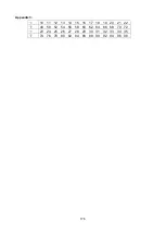
Page 166: ...176 Appendix 3 10 11 12 13 14 15 16 17 18 19 20 21 22 48 50 52 54 56 58 60 62 64 66 68 70 72 23 24 25 26 27 28 29 30 31 32 33 34 35 74 76 78 80 82 84 86 88 90 92 94 96 98 ...

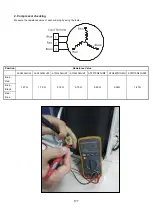
Page 167: ...sistance value of each winding by using the tester Position Resistance Value ASN98D22UFZ ASM135D23UFZ ATF235D22UMT ATF250D22UMT ATF310D43UMT ATQ420D1UMU ATM115D43UFZ2 Blue Red 1 57Ω 1 75 Ω 0 75 Ω 0 75 Ω 0 65 Ω 0 38Ω 1 87Ω Blue Black Red Blue ...

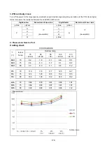
Page 168: ...ce value Red Black Several MΩ Red Black Several MΩ P N U N U V V W W Red 4 Pressure on Service Port Cooling chart COOLING MODE Indoor Temp Outdoor temp 75 23 89 85 29 44 95 35 105 40 56 115 46 11 BAR 70 8 2 7 8 8 1 8 6 10 1 BAR 75 8 6 8 3 8 7 9 1 10 7 BAR 80 9 3 8 9 9 1 9 6 11 2 PSI 70 119 113 117 125 147 PSI 75 124 120 126 132 155 PSI 80 135 129 132 140 162 MPA 70 0 82 0 78 0 81 0 86 1 01 MPA 75 ...

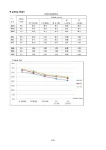
Page 169: ...BAR 55 30 3 28 5 25 3 22 8 20 8 BAR 65 32 5 30 0 26 6 25 4 23 3 BAR 75 33 8 31 5 27 8 26 3 24 9 PSI 55 439 413 367 330 302 PSI 65 471 435 386 368 339 PSI 75 489 457 403 381 362 MPA 55 3 03 2 85 2 53 2 28 2 08 MPA 65 3 25 3 00 2 66 2 54 2 33 MPA 75 3 38 3 15 2 78 2 63 2 49 Pressure bar Outdoor temp ...

Page 170: ... Disconnect the fan motor wire fan capacity wire room temperature sensor wire and evaporator temperature sensor wire 3 Screw off the screws to remove electronic control box 2 Remove the display board 1 Remove the cover of electronic control box Repeat the operation of step1 of No1 2 Disconnect the display board wire connected to PCB 3 Remove the sticker Four screws Connector Sticker 2 screws Plug ...

Page 171: ...rs connected to the PCB and remove the ground wire after remove the screw 2 Remove the PCB from the electronic control box 4 Remove the fan capacitor 1 Remove the cover of electronic control box Repeat the operation of step1 of No1 2 Disconnect the fan capacity wire Repeat the operation of step2 of No1 3 Screw off the screw to remover it Press the four fixing holders from four corners to remove th...

Page 172: ...emble the fan motor fixing clamps to remove the fan motor assembly and fan wheel assembly 8 Disassemble the fan wheels then you can remove the fan motor Press the clips to take off the volute shell Press Press 5 screws Rear cover board Total four screws at the left side and right side The fan motor assembly and fan wheel assembly can be removed after took off the 2screws used to fix the fan motor ...

Page 173: ...1 of No 5 2 Screw off the screws to remove the water collector assembly 7 Remove the evaporator 1 Remove the water collector Repeat the operation of No 6 2 Remove the evaporator sensor 3 Remove the pipe clamp board 4 screws 3 screws 3 screws Evaporator sensor 2 screws 3 screws Water collector assembly ...

Page 174: ...184 4 Remove the evaporator support board 5 Screw off the fixing screws to remove the evaporator 4 screws 1 screw ...

Page 175: ...tep1 of No 1 5 Remove the grille Screw off two screws Disconnect the display board wire and swing motor wire connected to the PCB Remove the grille 5 Loose the four screws and two wireropes then the panel can be disassembled 3 Remove the display 1 Open the grille Repeat the operation of step1 of No 1 2 Remove the grille Repeat the operation of step2 of No 2 Grill switch 2 screws 4 screws 2 wirerop...

Page 176: ...l Repeat the operation of step1 2 3 of No 2 2 Screw off 3 screws to remove the swing motor assy 3 Screw off 1 screws to remove the swing motor 5 Remove the PCB 1 Open the grille Repeat the operation of step1 of No 1 No need to remove the panel 2 Disassemble the electronic control box cover after remove the 2 screws 2 screws 4 screws 4 screws 3 screws 1 screw ...

Page 177: ...tep1 of No 1 No need to take down the panel 2 Remove the electronic control box cover Repeat the operation of step 2 of No 5 3 Pull out all the plugs or connectors connected to the electronic control box 4 Remove the electronic control box Remove the 2 screws to disassemble the electronic control box 7 Remover the fan 1 Repeat the operation of No 5 2 screws Pump RY2 Temp sensors Display board Swin...

Page 178: ... ring Release the 4 screws to disassemble it 3 Remove the fixing nut to disassemble the fan wheel 4 Pull out the fan wheel 8 Remove the fan motor 1 Repeat the operation of No 6 2 Remove the fixing board of fan motor wire 3 nuts 4 screws ...

Page 179: ... No 6 8 Screw off the 4 screws inside 4 holes 1 is under a protection cover to remove the water collecting assembly 9 Take out the water collecting assembly 10 Remove the draining pump 1 Remove the panel Repeat the operation of No 2 2 Remove the electronic control box Repeat the operation of No 6 3 Remove the water collecting assembly Repeat the operation of No 9 4 Disconnect the drain pipe 5 scre...

Page 180: ...ere are 2 screws under the supporter to fixing the pump Release them to take the pump out of the supporter 11 Remove the evaporator 1 Remove the water collecting assembly Repeat the operation of No 9 2 Remove the seal board of evaporator 3 Remove the evaporator fixing board 3 screws 4 screws ...

Page 181: ...191 4 Remove the evaporator fixing clamps to disassemble the evaporator Fixing clamps 1 screw ...

Page 182: ...or wire and evaporator temperature sensor wire 8 Screw off the screws to remove electronic control box 2 Remove the PCB 9 Remove the cover of electronic control box Repeat the operation of step1 of No1 2 Pull out all the plugs or connectors connected to the PCB and remove the ground wire after remove the screw Five screws Plug of room temperate sensor and evaporator temperature sensor Fan motor wi...

Page 183: ...ep1 of No1 7 Disconnect the reactance wire 8 Screw off the screw to remover it 4 Remove the drain pump 1 Remove the cover of electronic control box Repeat the operation of step1 of No1 2 Disconnect the drain pump wire 3 Screw off the screws to remover it Press the two fixing holders to remove the PCB 1 screw Reactance wire 4 screws Drain pump wire ...

Page 184: ...sassemble the fan wheels then you can remove the fan motor 6 Remove the water collector assembly 6 Remove the rear cover board Repeat the operation of step1 of No 5 7 Screw off the seven screws to remove the top cover then remove the water collector assembly 7 screws Press the clips to take off the volute shell Press 10 screws Rear cover board The fan motor assembly and fan wheel assembly can be r...

Page 185: ...n of No 6 11 Remove the evaporator sensor 12 Remove the pipe clamp board 13 Remove the evaporator support board 14 Screw off the fixing screws to remove the evaporator means there is no this part in some models Evaporator sensor 2 screws 4 screws 1 screw Water collector assembly ...

Page 186: ...wer breaker 2 Remove the big handle first then remove the top cover 3 screws 3 Remove the screws of front panel 7 screws 4 Remove the screws of the right side panel 11 screws 2 4 3 3 2 Fan ass y How to remove the fan ass y 1 After remove the Screws of front panel 7 screws Screws of top panel 3 screws 1 screws is under the big handle 3 screw of big handle ...

Page 187: ... fan and remove the fan 3 After remove the top cover Unfix the hooks and then open the electronic control box cover 4 Disconnect the connector for fan motor from the electronic control board 2 3 compressor T3 T4 T5 sensor Motor Electronic expansion valve 4 way valve ...

Page 188: ...221 5 Remove the four fixing screws of the fan motor then remove the motor 5 ...

Page 189: ...er finish work of item 1 and item 2 remove the connector for the compressor 6 Pull out the two blue wires connected with the four way valve 3 Pull out connectors of the condenser coil temp sensor T3 outdoor ambient temp sensor T4 and discharge temp sensor T5 1 2 3 ...

Page 190: ...223 4 Disconnect the electronic expansion valve wire from the control board 5 Remove the ground wires 6 Remove the wires 1 2 3 7 Then remove the electronic control box 5 6 ...

Page 191: ...d pipe 5 Then the four way valve ass y can be removed The picture of four way valve may be different from the one on your side 5 Compressor How to remove the compressor 6 After perform work of item1 3 Recover refrigerant from the refrigerant circuit 7 Remove the discharge pipe and suction pipe with a burner 8 Remove the hex nuts and washers fixing the compressor on bottom plate 9 Lift the compress...

Page 192: ...ditioner and turn OFF the power breaker 1 Remove the big handle first and then remove the top panel 3 screws 3 Remove the screws of front panel 6 screws 4 Remove the screws of the right side panel 8 screws 2 4 3 Screws of top panel 3 screws 1 screw is under the big handler 3 screws of the big handler 6 screws of front panel ...

Page 193: ...ing procedure 1 remove the hex nut fixing the fan and then remove the fan 2 Unfix the hooks and then open the electronic control box cover 1 2 compressor T3 T4 T5 sensor Motor Electronic expansion valve 4 way valve 2 Fan ass y How to remove the fan ...

Page 194: ... Remove the four fixing screws of the fan motor Then remove the fan motor 3 Electrical parts How to remove the electrical parts 1 After finish work of item 1 and item 2 remove the connectors for the compressor 2 Pull out the two blue wires connected with the four way valve 1 3 4 2 ...

Page 195: ...ndenser coil temp sensor T3 outdoor ambient temp sensor T4 and discharge temp sensor T5 4 disconnect the electronic expansion valve wire 5 Remove the grounding screw 6 Remove the Wires 1 2 3 Then remove the electronic control box 3 4 5 6 ...

Page 196: ...pipe 10 Then the four way valve ass y can be removed The picture of four way valve may be different from the one on your side 3 4 5 Compressor How to remove the compressor 1 After perform work of item1 3 Recover refrigerant from the refrigerant circuit 2 Remove the discharge pipe and suction pipe with a burner 3 Remove the hex nuts and washers fixing the compressor on bottom plate 4 Lift the compr...

Page 197: ...nel plate 1 Stop operation of the air conditioner and turn OFF the power breaker 2 Remove the top panel 3 screws 3 Remove the screws of front panel 9 screws 4 Remove the screws of the right side panel 8 screws 2 4 3 3 screws of top panel 9 screws of front panel 3 screws of big handle ...

Page 198: ...hen remove the fan 2 After remove the top cover Unfix the hooks and then open the electronic control box cover 2 T3 T4 T5 sensor wire Motor wire Electronic expansion valve Compressor wire 4 way valve wire Electric pipe heater and Crankcase electric heater 2 Fan ass y How to remove the fan ass y 1 ...

Page 199: ...motor Then remove the fan motor 3 Electrical parts How to remove the electrical parts 1 After finish work of item 1 and item 2 remove the connectors for the compressor and reactor 1 3 4 3 Disconnect the connector for fan motor from the electronic control ...

Page 200: ...denser coil temp sensor T3 outdoor ambient temp sensor T4 and discharge temp sensor T5 4 disconnect the electronic expansion valve wire 6 remove the electric heaters 3 3 4 2 2 Pull out the two blue wires connected with the four way valve ...

Page 201: ...234 6 Remove the grounding screw 7 Remove the Wires 1 2 3 or L1 L2 S Then remove the electronic control box 7 5 ...

Page 202: ... pipe 11 Then the four way valve ass y can be removed The picture of four way valve may be different from the one on your side 3 5 Compressor How to remove the compressor 1 After perform work of item1 3 Recover refrigerant from the refrigerant circuit 2 Remove the discharge pipe and suction pipe with a burner 3 Remove the hex nuts and washers fixing the compressor on bottom plate 4 Lift the compre...

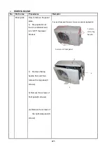
Page 203: ...peration of the air conditioner and turn OFF the power breaker 2 Remove the big handle first then remove the top cover 7 screws 3 Remove the screws of front panel 11 screws 4 Remove the screws of the right side panel 13 screws 2 4 3 Screws of front panel 11 screws Screws of top panel 3screws 1screws is under the big handle 4 screws of big handle ...

Page 204: ...an ass y 1 After remove the panel plate following procedure 1 2 Remove the nut fixing the fan and remove the fan 3 Unfix the hooks and remove the screws then open the electronic control box cover 2 3 fan Electronic control box compressor ...

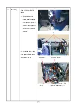
Page 205: ...nnector for fan motor from the electronic control board 5 Remove the four fixing screws of the fan motor then remove the motor 5 4 T3 T4 T5 sensor Pressure switch Compressor wire Electronic expansion 4 way valve Motor wire 5 ...

Page 206: ...er finish work of item 1 and item 2 remove the connector for the compressor 2 Pull out the two blue wires connected with the four way valve 3 Pull out connectors of the condenser coil temp sensor T3 outdoor ambient temp sensor T4 and discharge temp sensor T5 1 2 3 ...

Page 207: ...ect the pressure switch connector 5 Disconnect the electronic expansion valve wire from the control board 6 Remove the ground wires 7 Remove the wires 1 2 3 or L1 L2 S Then remove the electronic control box 6 7 5 4 ...

Page 208: ...d pipe 5 Then the four way valve ass y can be removed The picture of four way valve may be different from the one on your side 5 Compressor How to remove the compressor 1 After perform work of item1 3 Recover refrigerant from the refrigerant circuit 2 Remove the discharge pipe and suction pipe with a burner 3 Remove the hex nuts and washers fixing the compressor on bottom plate 4 Lift the compress...

Page 209: ... remove the fan ass y 1 Stop operation of the air conditioner and turn OFF the power breaker 2 Remove the screws of air outlet grille 8 screws 3 Remove the hex nut fixing the fan 4 Remove the fan 5 Remove the screws of top cover and remove the top cover 4 screws Screws of top cover ...

Page 210: ...move the fan motor after unfastening fixing screws 2 Panel plate How to remove the panel plate 1 Remove big handle 2 screws and water collector 2 screws Screws of Water collector Screws of big handle Screws of right rear panel 6 Remove the screws of right front side panel and remove the right front side panel 1 ...

Page 211: ...rom the IPM board 3 Disconnect following 8 pieces of connection wires and connectors between IPM and other parts IPM board PCB board DC Fan Driver board Screws of right rear panel 1 Remove two screws of terminal board and seven screws of right rear panel and remove the right rear panel CN2 yellow CN1 red CN6 black CN3 yellow U V W black CN9 10p white ...

Page 212: ...white CN12 Heatsink temperature sensor 2p red CN9 T3 T4 temperature sensor 2p 2p white CN15 Electronic expansion valve 6p red CN10 High and low pressure switch 2p 2p white Wires CN17 CN18 4 way valve blue blue CN19 CN20 connected to crankcase heating cable black red CN24 CN25 Electric heater of chassis orange orange CN1 L IN red or white CN3 N IN black CN1 CN3 CN17 CN18 CN19 CN20 CN24 CN25 ...

Page 213: ... and item 2 2 Extract refrigerant gas 3 Remove the sound insulation material and crankcase heating cable 4 Remove terminal cover of compressor and disconnect wires of crankcase electric heater and compressor from the terminal 5 Remove the discharge pipe and suction pipe with a burner 6 Remove the hex nuts and washers fixing the compressor to bottom plate 7 Lift the compressor ...

Page 214: ...ts from item 3 4 Remove fixing screw of the coil and remove the coil 5 Detach the welded parts of 4 way valve and pipe 6 The expansion valve How to remove the expansion valve 1 Perform work of item 1 2 2 Remove the electrical parts from item 3 3 Remove the coil 4 Detach the welded parts of expansion valves and pipes Coil Welded parts Expansion valves ...

Page 215: ...ct improvement Consult with the sales agency or manufacturer for details 2190 NW 89 Place Doral FL 33172 USA Tel 305 593 8358 www klimaire com Fax 305 675 2212 sales klimaire com The Klimaire logo is a registered Trademark of Klimaire Products inc Copyright 2019 Klimaire Products Inc ...

Reviews: