5
04.06.2019
explosion-proof duct fan
WP-11/Ex
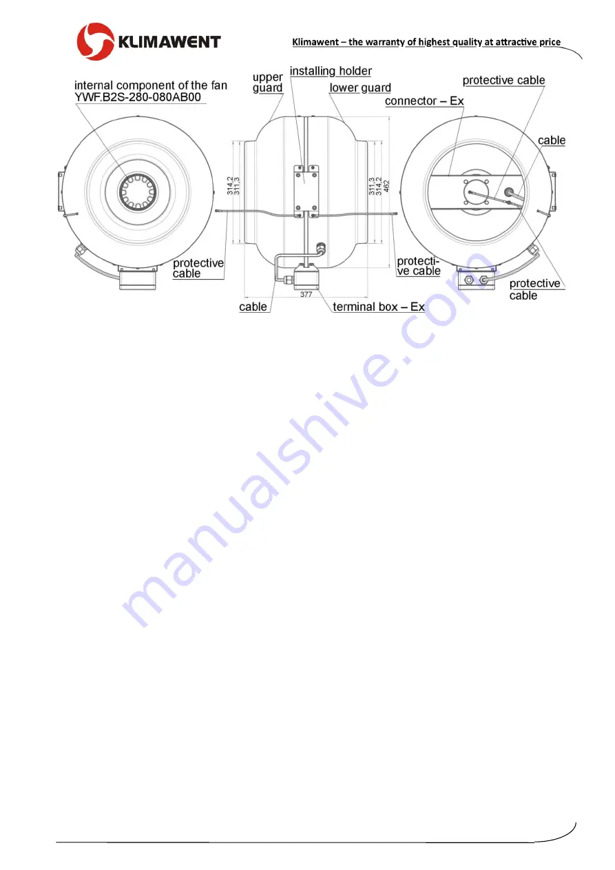
Fig. No.2
– WP-11/Ex – Structure and dimensions
5.
Structure and Function
WP-11/Ex consists of two bell-shape plastic (HIPS conducting) draw pieces. Both elements
are crewed together with larger perimeters, forming the area for the motor with a rotary stator.
The radial impeller is fastened to the stator. Free ends (of the two housing parts are suitable
to the standard diameters of rigid round ventilation ducts.
Outside the housing is located a terminal box (Ex execution) for connection to the 3x400V po-
wer supply. Additionally, the housing is equipped with a mounting plate, to install the fan at
the supporting structure
– by means of four M6 bolts.
Flow direction is indicated with an arrow on the fan housing. The fans have to be installed be-
tween the round ventilation ducts of appropriate diameter. The appliances feature small dimen-
sions and very silent work.
Isolating switches are additional equipment and are delivered upon separate order.
6.
Assembly and Start-up
Before the installing, and after the fan is taken out of the transport package, check the state
of the fan (if there are no damages that occurred during the transport). WP-11/Ex duct fans
are installed inside the rooms (indoor application), in vertical and horizontal round rigid ven-
tilation ducts of round section (see Table of dimensions).
The air flow is indicated by an arrow on the fan housing. The arrow shows how should the
fan be installed in the ventilation ducting (as a positioning). The fan housing should be fas-
tened to the ventilation ducts with rivets or plate screws.
Additionally, the connection “fan-duct” ought to be sealed with “silicone” or a sealing adhe-
sive tape. Apart from the
“fan-duct” fastenings, it is important to attach the fan to the suppor-
ting construction (4 bolts M6). This ought to be performed by
User on one’s own, with refe-
rence to local conditions.
Prior to the connection to the power supply system, make sure if the parameters of the exis-
ting system is in accordance with the parameters on the nominal data plate. In case of diffe-
rence it is not possible to carry out the connection.
The appliance ought to be connected to the supply
by operator on one’s own – whereby it
is important to select the sort and section of the supply cables and the protection from the
short-circuit- and overload effect, according to the local conditions.


