8
Explosion proof stationary fan
WPA-P-N/Ex 07.02.2017
Fan
Motor
rate
[kW]
Current
[A]
Motor type
Cable
W1, W2
Protective
cable G-Y
W3, W4
WPA-6-P-N/Ex
0,75
1,8
SLg 80-2A; 3x400V; 50 Hz
2760 r.p.m.; IMB35: BESEL
to be
selected
by User
H05V 1G6
WPA-8-P-N/Ex
1,5
3,5
SLh 90S; 3x400V; 50 Hz
2850 r.p.m.; IMB35: INDUKTA
WPA-10-P-N/Ex
4,0
7,5
SLg 112M-2; 3x400V; 50 Hz
2875 r.p.m.; IMB35: INDUKTA
Caution
: The steel plate for current-equilibrating connections
– as in
the Dwg. No 1012-017078 of mechanical documentation
– referring
the fans
WPA-10-D/Ex
;
WPA-10-E/Ex
.
Caution
:
1. Supply voltage: 3x400V; 50Hz
2. Continuous work S1
3. Ingress protection: IP56
4. Ambient temperature: -
20ºC up to +40ºC
5. Insulation class F
6. Connect the grounding cable of length 400mm, (ended with
a
KOI
terminal), to the fan housing.
7. Installations and devices for use in areas of
explosion risk
– should be executed according to
–
arrangements of the 2014/34/EC ATEX Directive,
–
valid regulations and standards.
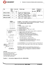
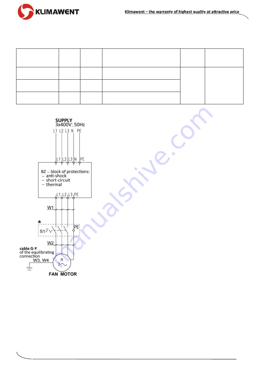
*
S1
isolating switch
– in Ex execution.
It is recommended to install it near the fan.
The application of the isolating switch is not obligatory
and depends on the decision of Investor.
Cables
W1
,
W2
have to be selected by Investor, with reference to
the fan motor rate, cable length, outline of the cable, voltage drop.
W3
,
W4
are cables for local equilibrating connections of
cross-section 6mm
2
, length 300 mm, ended with adequately
selected eye terminals, designed for connection to the fan
fitting pieces.
CAUTION
:
The motor windings must be connec-
ted according to the data on the
nominal data plate of the motor and the
connection diagram (placed on the
cover of the motor terminal box).
Fig. No.3
– Connection diagram of the fan WPA-P-N/Ex


