36
OPERATION AND MAINTENANCE MANUAL
DUCTLESS-ROOFTOP AIR HANDLING UNITS
EVO-RX
AND
EVO-RX HPM
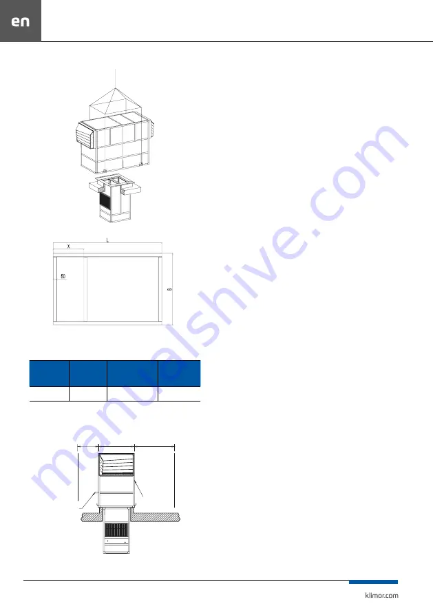
Fig. 9
Mounting of the EVO-RX air handling units on the roof base
Fig. 10
Base dimensions
Table No. 5
Unit frame dimensions for UOH and UOV versions
UNIT SIZE
TYPE OF THE
FRAME
MAXIMUM CROSS
WISE SUPPORT
SPACING X**
FRAME HEIGHT
0500
0800
channel
frame
650 mm
120 mm
4.2.2 Service space
To operate the EVO-RX air handling unit, service space
is required on both sides of the unit.
Kondensat
Kondensat
750
750
W+150
W+150
W
W
St
Strrona
ona
obslug
obslugow
owaa
Fig. 11
Space required for operating the air handling unit
4.2.3 Foundation, assembly and joining of blocks
Foundation of the unit on the roof is performed by
means of the crane on the previously made roof base..
Roof base should be made according to the description
in chapter 4.2.1.
The device is held in the roof plinth under its own
weight.
The unit must be installed in the following order:
• positioning of the seal on the upper side of the roof base,
• placing the indoor unit in the roof plinth hole,
• dismantling the eyebolts intended for carrying the in-
door unit (Fig. 7),
• positioning of the seal (self-adhesive gasket) on the
flange of the indoor unit,
• installation and appropriate positioning of the outdoor
unit on the flange of the indoor unit,
• screwing the outdoor unit with the flange of the indoor
unit,
• dismantling the transport handles of the outdoor unit,
• connecting the installation, starting the unit.
To seal the flange of the indoor unit with the roof base,
use a sealing compound (e.g. roofing material). Use the
gasket provided with the unit to seal between the unit
sections.
To seal the flange of the indoor unit with the roof base,
use a sealing compound (e.g. roofing material). Use the
gasket provided with the unit to seal between the unit
sections.
When installing the indoor unit in a roof base hole, pro-
tect the unit from scratches and other damage. It is rec-
ommended to use soft material spacers (felt, cardboard)
when sliding the unit into the hole. Attention should
also be paid to protruding elements (heater cover
clamps). If necessary, it is recommended to remove
them during installation.
All mounting points should be used for screwing the
EVO- RX sections..
The outdoor unit should be placed on the flange of the
indoor unit so that the screws connecting the sections
can be easily screwed in. Incorrect positioning of the
two sections in relation to each other will result in over-
tightening of the connecting bolts and damage to the
thread in the rivet nuts of the outdoor unit, which will
require replacing them.
4.2.4 Installations and their connection to the unit
After installing the air handling unit, the electrical,
heating and cooling system can be connected (the
scope of work depends on the functions performed).
Condensate
Service
side
Summary of Contents for EVO-RX
Page 27: ...25 NOTATKI...
Page 28: ...SERWIS SERVICE 48 587839954 48 500087227 serwis klimor com...
Page 53: ...51 NOTES...
Page 54: ...SERWIS SERVICE 48 587839954 48 500087227 serwis klimor com...
Page 55: ...EVO RX EVO RX HPM KLIMOR...
Page 57: ...55 1 EVO RX EVO RX HPM KLIMOR KLIMOR 2 2 1 EVO RX RX HPM 45 C 1...
Page 61: ...59 3 1 4 3 4 1 1...
Page 62: ...60 EVO RX EVO RX HPM 4 4 1 EVO RX 6 7 5 6 7 5 KLIMOR...
Page 66: ...64 EVO RX EVO RX HPM 100OC powr t zasilanie przep powietrza 14 10 20 15 STAD STAD...
Page 73: ...71 5 5 EVO RX HPM Modu steruj cy UTY VDGX 24 DX KIT 25 0500 UTY VDGX Control Unit UTY VDGX...
Page 76: ...74 EVO RX EVO RX HPM 8 13 1 2 3 DX 4 5...
Page 77: ...75 9 9 1 15 9 2 90 70 C 9 3 9 4 9 5 30 IP54 10 EVO S IP65...
Page 78: ...76 EVO RX EVO RX HPM 11...
Page 79: ...77...
Page 80: ...78 EVO RX EVO RX HPM...
Page 81: ......


