background image


OPERATION AND MAINTENANCE MANUAL 

DTR MCK v.2.4 

PAGE 

GDYNIA 

MODULAR AIR HANDLING UNITS   

MCKS, MCKH, MCKP


2017 EN 

10/45 


KLIMOR Spółka z ograniczon

ą

 odpowiedzialno

ś

ci

ą

 Sp.k., 81-035 Gdynia, ul. B. Krzywoustego 5 

Fax: (+48 58) 783-98-88; Tel.: (+48 58) 783-99-99  
Service -


Fax: (+48 58) 783-98-88; Tel.: (+48 58) 783-99-50/51 Mobile: (+48) 510 098 081 

Information in this document is subject to change 

email: 

klimor@klimor.pl

 -


office 

serwis@klimor.pl


-


service 


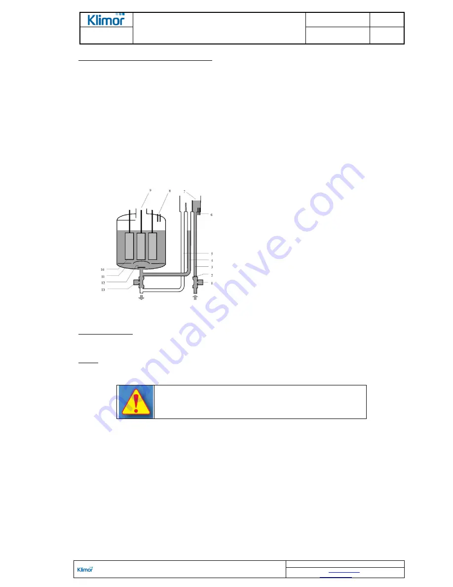
Humidifier with an electrical steam generator  

The  humidifiers  with  electrical  steam  generator  use  passage  of  current  between  electrodes  immersed  in  water,  to 
heat up water and generate water steam. To enable passage of current between the electrodes, it is necessary to 
use water containing mineral elements. The recommended composition of the water: 
Required water parameters: 
pH reaction: 7÷8.5 
- conductivity: 350÷1250 uS/cm 
- hardness: 100÷400 mg/l CaCo3 
- iron and magnesium: 0,2 mg/l Fe+Mg 
- silica: max 20 mg/l SiO2 
- no organic contamination 
- supply pressure: 1÷6 bar 
- temperature: 1÷40°C 
- water flow according to requirements of a particular generator    

 
Higher  concentration  of  mineral  elements  in  water  will  lead  to  premature  damage  of  electrodes  and  lower 
concentration will cause drop of capacity of the steam generator     


1.  Supply solenoid valve 
2.  Flow limiter 
3.  Supply pipe 
4.  Filling pipe 
5.  Overflow pipe 
6.  Electrodes for conductivity measurement 
7.  Supply reservoir  
8.  Protection against excessive water level 
9.  Steam output 
10. Electrodes 
11. Cylinder 
12. Water filters 
13. Drain solenoid valve 


Figure No. 7

 Construction of the electrical water steam generator


Operation principle: 
Once the supply valve is opened water flows through the supply reservoir into the cylinder. Once the cylinder is filled 
the electrodes are heated and steam generation proceeds. Required steam generator capacity is achieved by setting 
with the automatics control system an appropriate value of the current passing through the electrodes.  

NOTE! 
Type of a steam generator, amount and size of lances 

– 

all these parameters are determined individually for 

a particular AHU and required amount of steam. 


Method of starting up and operating humidifiers (water humidifiers, process 

steam humidifiers and electrical steam generators) should be carried out 

based on the instructions supplied by the humidifier manufacturer. 


2.3.2.4 WC, DX cooling block 

The task of this block is to lower the air temperature down to the temperature required according to the design data. 
This task is accomplished by the water cooler, glycol cooler or direct expansion cooler (DX). 
Standard cooler consists of a galvanized steel sheet casing and CuAl package with copper pipes and aluminum fins. 
Manifolds and connectors are made of copper or steel. 
The  water and glycol exchanger is equipped with plugs: drain plug and venting plug. During assembly of hydraulic 
system it is recommended to install drain and vent valves at the pipes leading to the heat exchanger. 
When connecting coolers to the supplying system it is necessary to consider recommendations listed in the section 6. 
A droplet separator is installed downstream the cooler to catch water drops.  
In  sectional coolers, in  versions  with  double  exchangers,  the  droplet  separator  is  installed  downstream  the second 
cooler. 
Under the cooling block there is located a drip tray with a connector to drain off the condensate, led to the operational 
side. In case of the AHU size 11 there is also provided another connector leading to the opposite side. 
Drain  traps  are  also  provided  and  please  make  sure  to  install  them  in  accordance  with  the  guidelines  listed  in  the 
point 6.2.5 
A cooler assembly and disassembly method in the AHU acc. to 

Fig No. 3

Summary of Contents for MCKH

Page 1: ...stego 5 Fax 48 58 783 98 88 Tel 48 58 783 99 99 Service Fax 48 58 783 98 88 Tel 48 58 783 99 50 51 Mobile 48 510 098 081 Information in this document is subject to change email klimor klimor pl office...

Page 2: ...TION OF THE MCKS RX AHU 23 6 2 AHU INSTALLATION AND CONNECTION 24 6 2 1 AIR SYSTEM 24 6 2 2 CONNECTING ELECTROSTATIC FILTERS 25 6 2 3 CONNECTION OF HEATING AND COOLING BLOCKS 25 6 2 4 CONNECTING THE H...

Page 3: ...over all information in relation to the system and supplementary components which should be provided with dedicated operation manuals 2 GENERAL TECHNICAL DESCRIPTION 2 1 Intended application Modular a...

Page 4: ...e MCK AHUs as standard are designated with a short code according to markings shown in the diagram 1 Diagram No 1 Short MCK AHU designation 1 2 3 4 5 TYPE MCKS standard MCKH hygienic MCKP swimming poo...

Page 5: ...Water humidification ES Inspection Mixing Separation MX Mixing Recirculation SL Short silencer Long silencer VF Fan PR Cross flow heat exchanger CPR High performance hybrid exchanger RR Rotary heat ex...

Page 6: ...lled inside the AHU Dismantling opening disassembling or cutting out elements of the supporting structure carried out by the user may lead to the AHU depressurization and loss of warranty The supporti...

Page 7: ...he opposite side Drain traps are also provided and please make sure to install them in accordance with the guidelines listed in the point 6 2 5 All AHU rectangular inlets and outlets are equipped with...

Page 8: ...owed the device may be damaged For AHUs with the heat recovery the heating module sections can be equipped with internal bypass chambers of the heat exchanger with a control damper The side flow is us...

Page 9: ...hen the humidifier was selected Requirements related to the water humidifier installation are provided in section 6 2 4 1 Trickling filter 2 Water distributors 3 Water distributors pipes 4 Float 5 Flo...

Page 10: ...re heated and steam generation proceeds Required steam generator capacity is achieved by setting with the automatics control system an appropriate value of the current passing through the electrodes N...

Page 11: ...re fitted in rails with gaskets and a strip clamp fasten with an eccentric connection mechanism At the filter replacement it is recommended to replace self adhesive gasket attached inside the rail The...

Page 12: ...n 2 302 Min set Hz value FZ min Table No 9 Hz 303 Max set Hz value FZ max Table No 9 Hz 341 Acceleration time in s from min to max preset value 30 s 342 Breaking time in s from min to max preset value...

Page 13: ...ally covered with a layer of hygroscopic material The heat exchanger should be equipped with anti frost system to protect the unit against consequences of extensive chilling of the air exhaust part of...

Page 14: ...m with the circulating pump option Design of the heat exchangers is similar to the Cu Al water coolers and heaters A heat exchanger located in extracted airflow cooler absorbs the heat from the air an...

Page 15: ...8 15 INST GLKL LE_HE 10 PUMP CM10 3 5 50 2 2 2895 8 15 INST GLKL LE_HE 11 PUMP CM15 2 5 50 2 2 2895 8 15 Sets with the glycol system as standard are supplied in empty condition Scope of pipeline assem...

Page 16: ...below shows minimum amounts of air depending on a AHU size and rows numbers of the exchanger which serves as a condenser and cooler Higher rows number is able to accept return a given power at lower a...

Page 17: ...re gauges are equipped with an automatic re set device Additionally there are low and high pressure gauges with automatic reset device in tandem set Once ac tivated they reduce the output in order to...

Page 18: ...he drainage line only in systems with one compressor 9 Four way valve 10 DX container in 160 size systems 11 Ball valve for DX fill up 12 Filter dehydrator 13 Solenoid valve 14 Eyehole 15 Expansion va...

Page 19: ...adjustment valve 8 Check valve at the drainage line 9 Four way valve 10 DX container in 160 size systems 11 Ball valve for DX fill up 12 Filter dehydrator 13 Solenoid valve 14 Eyehole 15 Electronic ex...

Page 20: ...d ensure minimum amounts of air given in Table No 10 The condition of air filters should be monitored Contamination of air filters may cause considerable drops in airflow rate Monitoring the cooling s...

Page 21: ...ipe or hook at tachment and lifting using belts In case of separated air supply exhaust AHUs the upper part is lifted using additional holders which are screwed to lower part of the framework The hold...

Page 22: ...t Sheet thick ness Framework height 01 02 03 Foundation corner 1500 mm 2 mm 120 mm 04 05 Framework made of channel bars 1500 mm 2 mm 120 mm 06 07 08 09 10 11 Framework made of channel bars 1200 mm 2 5...

Page 23: ...nce the sections are connected requires installation of a sealing cover channel bar and sealing with silicone according to Fig No 49 If the sealing cover is not installed it may lead to local condensa...

Page 24: ...can proceed with connection of air ducts electrical power supply heating and cooling ducts as well as humidifying system scope of work depends on the AHU functionality 6 2 1 Air system The AHU with s...

Page 25: ...ring diagram of electrostatic filters 6 2 3 Connection of heating and cooling blocks Water heaters and coolers Exchangers should be connected in such a way as to prevent stresses that may cause mechan...

Page 26: ...h the qualification certificate issued by the manufacturer Please contact Klimor service department or the burner s manufacturer to schedule the start up The following conditions must be met before st...

Page 27: ...opening of the bypass damper if equipped setting the flow defined in the AHU Data Sheet 6 2 4 Connecting the humidification block a water humidifier with a trickling filter 1 Water supply 2 Cut off va...

Page 28: ...re Figure No 29 Connection of water supply and return from the humidifier with an electrical steam generator Requirements 1 It is required to install a cut off valve and mechanical filter not provided...

Page 29: ...t up While connecting motors and other electrical devices and components it is necessary to strictly follow the H S re quirements stated in appropriate standards and regulations related to the install...

Page 30: ...er with their accessories 4 In the water humidifier with the trickling filter it is necessary to check the pomp attachment and operating condition of the float valve its closing operation and level 5...

Page 31: ...start up the AHU only with closed doors of the fan block Take into consideration the instructions stated in section 9 Table No 16 EC fans connection diagram description Fig No 35 No Cable no Intended...

Page 32: ...and motor cleanliness clean if necessary after 12 month period Check cleanliness of heat exchangers and heat recovery exchangers using a vacuum cleaner soft brush or blow with compressed air Check cl...

Page 33: ...in detergents depending on a type of contamination rinsing with clean water and drying Depth of the cartridge filters is 50mm Table No 18 Dimensions and number of cartridge filters in AHUs Size confi...

Page 34: ...Example of bag filters class G4 designation for AHUs size 4 FK 4 300 6k 592x592 1 FK 4 300 6k 592x287 2 FK 4 300 3k 287x287 1 Example of bag filters class F9 designation for AHUs size 8 FK 9 500 8kw 5...

Page 35: ...eater Condition of the heater fins should be checked less frequently every 12 months however it is recommended to do it while replacing the filters When the exchanger is contaminated it should be clea...

Page 36: ...ary exchanger sections the neighboring sections should be secured Clean with a vacuum cleaner with a soft suction nozzle on the side of air inlets or blow through with air in the direction opposite to...

Page 37: ...ing Too low medium evaporation temper ature Rise medium evaporation temperature Escaping cooling medium Leakage at screwed or soldered con nections Locate the leakage and seal it properly 4 Cooling bl...

Page 38: ...lves thermometers and manometers near the devices c In case of heaters it is recommended to apply bypass of the control valve using the 15 pipe with manual control valve or adjustable orifice to allow...

Page 39: ...0 10 mm It is screwed to the damper or AHU s profiles As sembly on the front or other wall np side wall once the AHU is equipped with an empty section It is possible to in stall additional elbows or s...

Page 40: ...e Fax 48 58 783 98 88 Tel 48 58 783 99 50 51 Mobile 48 510 098 081 Information in this document is subject to change email klimor klimor pl office serwis klimor pl service 100 mm 100 mm A A Falownik F...

Page 41: ...eyeholes Inspection eyeholes portholes 200 are located in front covers and panels in sections equipped with illumination They enable without switching off the AHU assessing the contamination degree of...

Page 42: ...aded connectors Connection of these elements should be carried out so that it is possible to remove each exchanger and humidifier from the AHU d Each AHU set is equipped with drip gutter for inter nal...

Page 43: ...ecommended to avoid locating the air intake in vicinity of the air exhaust cooling towers sources of odors or harmful gases as well as streets car parks and areas with external thermal load The design...

Page 44: ...s required for the security designation 12 6 The tray below the heat recovery exchanger is made of stainless steel sheet 12 7 The blades of the exchanger droplet separator are made of PPTV profiles 12...

Page 45: ...dynia ul B Krzywoustego 5 Fax 48 58 783 98 88 Tel 48 58 783 99 99 Service Fax 48 58 783 98 88 Tel 48 58 783 99 50 51 Mobile 48 510 098 081 Information in this document is subject to change email klimo...

Reviews: