OPERATION AND MAINTENANCE MANUAL
DTR MCK v.2.4
PAGE
GDYNIA
MODULAR AIR HANDLING UNITS
MCKS, MCKH, MCKP
2017 EN
15/45
KLIMOR Spółka z ograniczon
ą
odpowiedzialno
ś
ci
ą
Sp.k., 81-035 Gdynia, ul. B. Krzywoustego 5
Fax: (+48 58) 783-98-88; Tel.: (+48 58) 783-99-99
Service -
Fax: (+48 58) 783-98-88; Tel.: (+48 58) 783-99-50/51 Mobile: (+48) 510 098 081
Information in this document is subject to change
email:
klimor@klimor.pl
-
office
serwis@klimor.pl
-
service
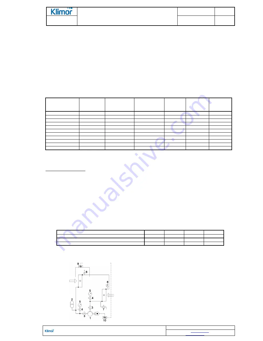
Increasing resistance at the glycol cooler, caused by frosting, activates the pressure gauge and sends a signal to the
control system. The inverter lowers down frequency of the motor, which reduces the pump output and increases the
medium temperature in the system.
NOTE! As standard, the glycol heat exchanger block is delivered without the anti-frost system. Type of the system is
determined by an AHU or control system designer. Pressure system is recommended.
The pressure gauge setting should be 150% of the nominal air pressure drop at the heat exchanger. Nominal value
of the pressure drop is provided in the AHU technical data.
Settings of the inverters should be performed in line with instructions provided in section 2.3.2.7 (table no. 7 and No.
8)
,
however, data of the pumps motors should be applied from the table no. 10.
Wiring of inverters make according to their respective OMMs.
If the AHU has been delivered together with the Klimor control system, do not use these settings. Please use
information provided in corresponding control system OMMs.
Table no. 10
The parameters required for correct setting of the pump inverter
Symbol of glycol
system
Symbol of
pump
Min. motor
operation
frequency Fz min
[Hz]
Max motor
operation
frequency, FZ max
[Hz] [Hz]
Rated motor
output
[kW]
Rated motor
RPM
[rpm]
Rated motor
current
[A]
INST.GLKL.LE_HE 1
PUMP CM1-2
5
50
0,46
2790
2,2
INST.GLKL.LE_HE 2
PUMP CM1-2
5
50
0,46
2790
2,2
INST.GLKL.LE_HE 3
PUMP CM1-4
5
50
0,46
2790
2,2
INST.GLKL.LE_HE 4
PUMP CM3-3
5
50
0,46
2790
2,2
INST.GLKL.LE_HE 5
PUMP CM3-5
5
50
0,65
2790
3,1
INST.GLKL.LE_HE 6
PUMP CM5-6
5
50
1,2
2840
5,2
INST.GLKL.LE_HE 7
PUMP CM10-2
5
50
1,2
2840
5,2
INST.GLKL.LE_HE 8
PUMP CM10-2
5
50
1,2
2840
5,2
INST.GLKL.LE_HE 9
PUMP CM10-3
5
50
2,2
2895
8,15
INST.GLKL.LE_HE 10
PUMP CM10-3
5
50
2,2
2895
8,15
INST.GLKL.LE_HE 11
PUMP CM15-2
5
50
2,2
2895
8,15
Sets with the glycol system as standard are supplied in empty condition. Scope of pipeline assembly to be carried out
by Klimor in each case is determined while submitting an order. It has to be filled with glycol before starting the sys-
tem.
System filling procedure:
1.
Connect a manual or electrical pump to the #8 drain valve. Check opening of all ball valves in the system.
2.
Fill up the glycol gradually so that pressure at the #10 manometer does not exceed 0,25 MPa. The system is equipped with a safety valve
with the 0,3 MPa setting.
3.
Watch the breather once some amount of glycol is supplied. Releasing air indicates removing air from the system. Lack of air bubbles
means that you can fill some more glycol to the system. Repeat steps 2 and 3 till the system is filled with appropriate amount of glycol.
4.
During the filling procedure open the solenoid valve once in order to vent the bypass.
5.
The circulating pump before startup has to be primed with medium in line with the manufacturer's OMM documentation.
NOTE!
Strictly follow the instructions regarding glycol type and concentration stated in the AHU Data Sheet. Glycol type provided
depends on the AHU intended use. Ethylene glycol is dangerous for people and can be used only in facilities which have
received appropriate approval. In hygienic AHUs it is recommended to use propylene glycol.
Glycol concentration determines the freezing temperature
–
too low concentration value (and in turn
–
freezing tempera-
ture) can lead to permanent damage of the system and glycol leakage.
Table No. 11
Initial freezing temperature for ethylene and propylene glycol
Initial freezing temperature [
°
C]
-15
-20
-25
-35
Ethylene glycol concentration (% volume)
28
35
40
48
Initial freezing temperature [
°
C]
-15
-20
-25
-35
Propylene glycol concentration (% volume)
33
37
42
60
Glycol concentration stated in the table initiates the freezing process in a given temperature. The concentration in the sys-
tem for a given temperature should be higher in order to enable safe system operation.
1. Circulation pump
2. Expansion vessel
3. Ball cut-off valve
4. Solenoid valve
5. Solenoid cut-off valve
6. Automatic breather
7. Manometer tap
8. Drain valve
9. Pressure gauge
10. Manometer
11. Safety valve
Figure No. 9
Glycol system diagram
automatic control


