OPERATION AND MAINTENANCE MANUAL
DTR MCK v.2.4
PAGE
GDYNIA
MODULAR AIR HANDLING UNITS
MCKS, MCKH, MCKP
2017 EN
29/45
KLIMOR Spółka z ograniczon
ą
odpowiedzialno
ś
ci
ą
Sp.k., 81-035 Gdynia, ul. B. Krzywoustego 5
Fax: (+48 58) 783-98-88; Tel.: (+48 58) 783-99-99
Service -
Fax: (+48 58) 783-98-88; Tel.: (+48 58) 783-99-50/51 Mobile: (+48) 510 098 081
Information in this document is subject to change
email:
klimor@klimor.pl
-
office
serwis@klimor.pl
-
service
8.Length of the pipe between the steam generator and lance cannot exceed 4 meters.
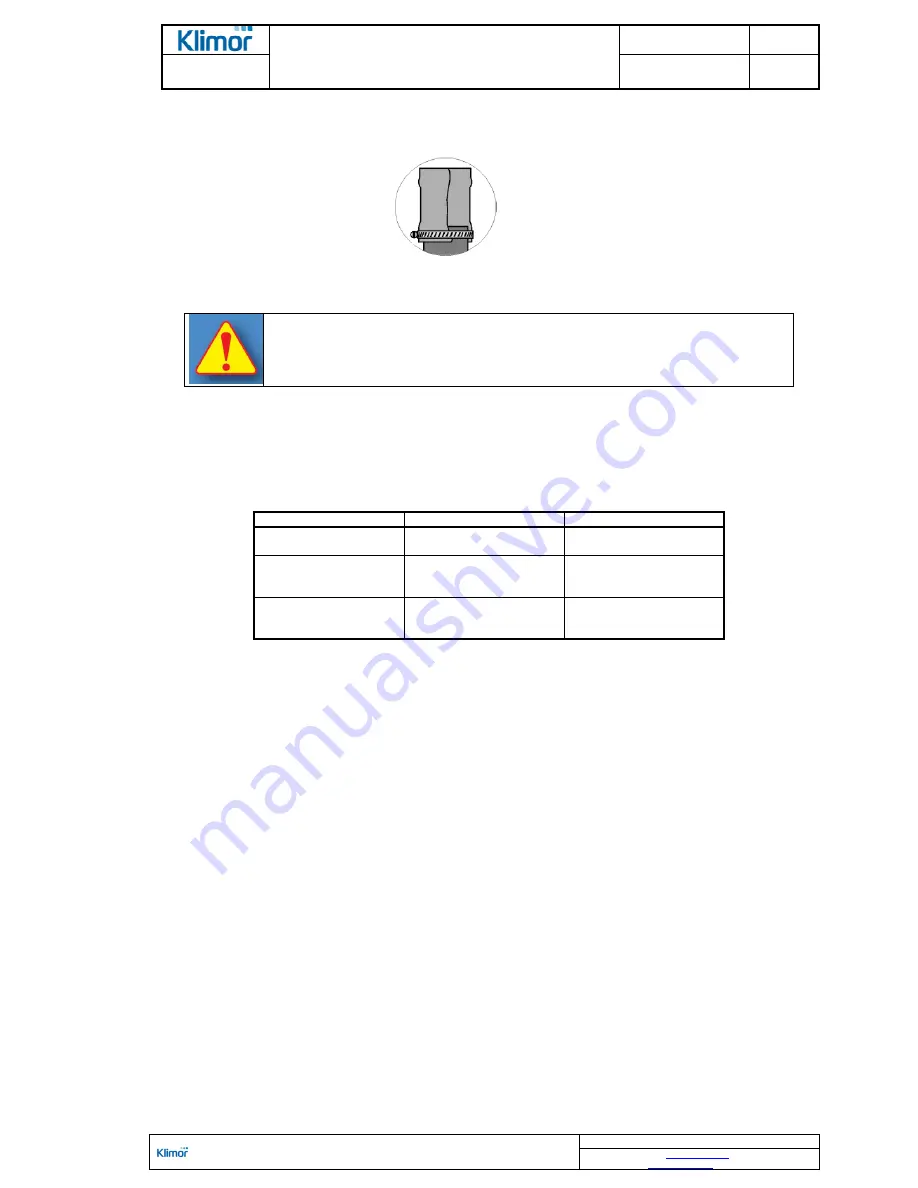
9.The pipe installation using a screw clamp Figure No. 31.
Figure No. 31
Observe instructions of the humidifier's manufacturer during the assembly.
When connecting exchangers and humidifiers it is necessary to pay attention to the
position of the pipes being installed, so that in case of removal of one exchanger
there is no need to remove connecting pipelines of other block and so that they do
not hinder opening the access doors as well as access to the AHU devices at its op-
erational side.
6.2.5 Electrical connection
It is possible to mount chokes for providing power supply to electrical motors and its grounding in the fan block casing
and the water humidification block with trickling filter and pump (if equipped) and for the internal glycol system's pump
on the operation side. The chokes are installed at fixed profiles and covers.
Table No. 15
Choose size depending on the AHU size
AHU size
Motor output [kW]
Choke size
01
÷
03
< 4
4
÷
8
P16
P20
04
÷
07
< 4
4
÷
8
8
÷
24
P16
P20
P27
08
÷
09
< 8
8
÷
24
>24
P20
P27
P32
Two supply chokes are installed for one-speed motors from N
S
= 5,5kW and for two-speed motors.
Before connecting a motor to the system it is necessary to check the winding resistance in order to find out if it has
not been destroyed due to moisture during storage.
Failure to comply with this may lead to motor damage (by burning) during the start-up.
While connecting motors and other electrical devices and components it is necessary to strictly follow the H&S re-
quirements stated in appropriate standards and regulations related to the installation and operation of electrical de-
vices. The electrical system should conform to requirements stated in the following standards and regulations (PN-
58/E-05012; PN-57/E-05022; PN-55/E-06000. The regulations related to construction of electrical devices of the Min-
ing and Energy Ministry).
If the AHU electrical switchboard is located in a different room than the AHU, it is mandatory to install the
START/STOP switch in the room where the device is going to be installed (as close to the AHU as possible) to ena-
ble service turn off of the AHU. Service switches sending ON/OFF signal to the AHU control system constitute stand-
ard AHU equipment.
All operations listed in the points 6.2.1
–
6.2.5 should be carried out in line with individual schedules and
documents and they should be carried out by personnel authorized to do these operations. It is also neces-
sary to take into account the assembly and design requirements stated in point 9.
6.2.6 Draining out condensate
The tubs of the recirculation block, cooling block, humidifier block there are drainage connectors installed which are
located outside the AHU.
For AHUs size 11, due to the tray width, the connectors are located at both AHU sides.
The flanges should have drain traps mounted to them to ensure appropriate condensate drainage and prevent air
suction. The traps are included in standard AHU delivery.
The trap used is an all-purpose device and may work on the suction (pressure below atmospheric) and pump (pres-
sure above atmospheric) side of the fan. It is only required that assembly works allow for the correct flow direction on
the condensate installation -
appropriate direction is shown on the device lid.
For a trap working on pressure below atmospheric an appropriately high terminal should also be made out of
supplied PVC pipes, working out value X where the trap is going to operate.


