OPERATION AND MAINTENANCE MANUAL
DTR MCK v.2.4
PAGE
GDYNIA
MODULAR AIR HANDLING UNITS
MCKS, MCKH, MCKP
2017 EN
31/45
KLIMOR Spółka z ograniczon
ą
odpowiedzialno
ś
ci
ą
Sp.k., 81-035 Gdynia, ul. B. Krzywoustego 5
Fax: (+48 58) 783-98-88; Tel.: (+48 58) 783-99-99
Service -
Fax: (+48 58) 783-98-88; Tel.: (+48 58) 783-99-50/51 Mobile: (+48) 510 098 081
Information in this document is subject to change
email:
klimor@klimor.pl
-
office
serwis@klimor.pl
-
service
Starting up the AHU with not adjusted system has to be carried out
with closed damper at the air inlet and with closed doors of the fan
block.
After adjustment you can start up the AHU only with closed doors of the fan block.
Take into consideration the instructions stated in section 9.
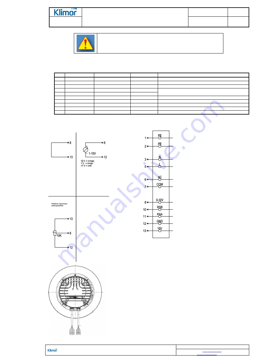
Table No. 16
EC fans connection diagram description (
Fig. No. 35
)
No.
Cable no.
Intended application
Color
Function
1
1, 2
PE
Green-yellow
Ground
2
3
N
Blue
Neutral power lead
3
5
L
Black
Hot (live) power lead
4
6
NC
White 1
State relay, open -
failure, max. 250V/2A 10 mA
5
7
COM
White 2
6
8
0-10V
Yellow
Analog input (set value); 0÷10 V; Ri=100k
Ω
;
7
10
RSB
Brown
RS485 input, Modbus protocol, RSB
8
11
RSA
White
RS485 input, Modbus protocol, RSA
9
12
GN
Blue
Ground of the control circuit, SELV
10
13
+10V
Red
Reference v10V +/-3%;
Figure No. 35
Diagram of the fan electrical connection with integrated EC motor.
User circut
Max speed speed adjusted with external
0-10V signal
Fan cables


