background image

User's Manual 

LINE 212-6 / LINE 212-9 

KLING & FREITAG GMBH ©2003 - 2005 

Version 5.0, 23.03.2006 

Seite 9 von 37 


3.


Important Notes for the ‘Outdoor’ Option 

Speakers with the option ‘Outdoor Mobile’ and ‘Outdoor Installation’ have been opti-
mised for outdoor use. They withstand temperature fluctuations in moderate climate 
zones and do not accumulate condensation water.  

In order to guarantee the longevity and safety of the speakers, the speakers with the 
option ‘Outdoor’ must still be protected from direct effects of the weather. 

They should be installed, for example, under a roof so that they also have sufficient 
protection from driving rain from the side and direct sunlight. 


3.1 


‘Outdoor Mobile’ 

Version for mobile outdoor use under roofs. 
Features like standard version but with the following extras: 


multi-layered, temperature and UV-resistant high-tech PU marine primer, 


final coating with highly resistant structured 2K paint in RAL colours, 


waterproofed diaphragms and electronic components protected against cor-
rosion with protective coating. 


3.2 


‘Outdoor Installation’ 

Version for fixed outdoor installations under roofs.  
Features like 'Outdoor Mobile', but with the following differences: 


No handles, feet, stacking foot grooves and locking profile for transport 
cover. 


Stainless steel flying points M 10 x 18 instead of ‘allsafe JUNGFALK’ flying 
points (positions and load capacity are the same) 


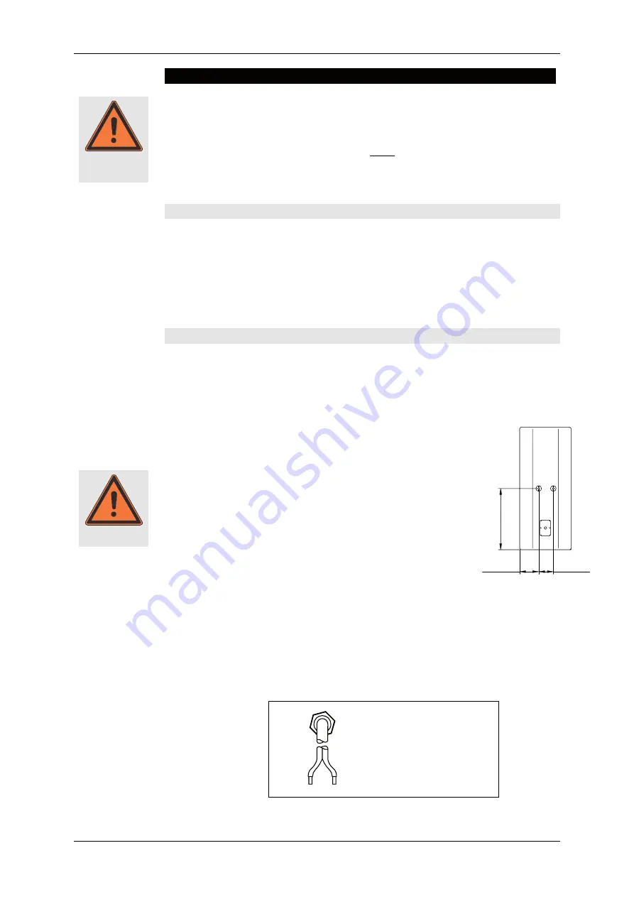
Instead of rear mounted flying tracks: two stainless steel 
thread inserts M 10 x 18 as flying points (load capacity 60 
kg / point) 


Tighten all screwed connections on the speaker and 
protect them against coming loose. 


Single stainless steel grille instead of parted steel grille. 

a.


The complete grille must be removed when turning the horn. Remove 
the screws on the grille. 


Foam covering behind the grille. 


Visible screws made of stainless steel. 


Stainless steel connecting terminal with single PG cable fitting, 
Ø 13 mm 

Connector: 


Warning 


Warning 

bl = blue 
bn = brown 

1-

bl

2+

bn

507,5 mm

159 mm

122 mm

Summary of Contents for LINE 212-6

Page 1: ...106 F weicht in Form und Aussehen von dieser Abbildung ab KLING FREITAG GmbH Junkersstrasse 14 D 30179 Hannover PHONE 49 0 511 96 99 70 FAX 49 0 511 67 37 94 www kling freitag de Important Information Please Read before Use K F LINE 212 6 9 User s Manual Version 5 0 Released 08 09 2005 ...

Page 2: ...User s Manual LINE 212 6 LINE 212 9 KLING FREITAG GMBH 2003 2005 Version 5 0 23 03 2006 Page 2 of 37 ...

Page 3: ...ructions may cause minor injuries or cause property damage Important This symbol gives instructions for the proper use of the described prod ucts Not following these instructions may cause malfunctions or prop erty damage Information about this User s Manual User s Manual LINE 212 6 9 Version 5 0 08 09 2005 by André Figula Kling Freitag GmbH 1995 2005 all rights reserved All specifications in this...

Page 4: ...he Coverage Pattern 15 8 Mounting Instructions for Speakers 16 8 1 Proper Arrangement of the Loudspeakers 16 8 2 Arrayed Speaker Systems Cluster 17 8 3 LINE 212 Systems on Top of SW 215E 18 9 Operations with the K F C2 Controller 19 9 1 Operations with Additional Bass Systems via C2 20 9 1 1 Line 212 via C2 and Bass B10 via C10 Controller 20 9 1 2 Line 212 and Bass B10 via C2 in 2 Way Active Mode ...

Page 5: ...Damage to Paint Changing the Front Foam 28 14 Technical Specifications 29 14 1 LINE 212 6 29 14 2 LINE 212 9 30 15 Measuring Charts 31 15 1 LINE 212 6 31 15 2 LINE 212 9 33 16 Dimensions 35 17 Accessories 36 18 Regulations for Disposal 37 18 1 Germany 37 18 2 EU Norway Island and Liechtenstein not Germany 37 18 3 Other countries 37 18 Included Safety and Mounting Instructions for Loudspeakers and ...

Page 6: ...ear they must be replaced immediately Furthermore screwed connections of supporting parts must be checked routinely Protecting the speakers operating safety In general audio signals should not be overdriven This may be caused by mixing consoles equalizers effect equipment etc and should be indicated on this equipment When a power amplifier is overloaded at the output clipping then the amplifier sh...

Page 7: ... direct sunlight where the devices are exposed to high moisture or rain where the devices are exposed to strong vibrations and dust Damage caused by the speakers magnetic fields Speakers are permanently surrounded by a magnetic field even when they are not operating Therefore during transport and placement of the speakers it is important to ensure that there is always approx 1 m between the speake...

Page 8: ...oor use under roofs Special finish in RAL colours LINE 212 6 SP Version with integrated power amplifier technology SP speakers are shipped with a separate user s manual 2 2 LINE 212 9 Short description 2 1 way completely horn loaded full range speaker system with bass reflex tuning Integrated passive crossover with patented FLC technology corrects delay times and phase Operations via specific syst...

Page 9: ...ly resistant structured 2K paint in RAL colours waterproofed diaphragms and electronic components protected against cor rosion with protective coating 3 2 Outdoor Installation Version for fixed outdoor installations under roofs Features like Outdoor Mobile but with the following differences No handles feet stacking foot grooves and locking profile for transport cover Stainless steel flying points ...

Page 10: ...with two wire ropes or chains which are independent of one another Furthermore the systems no matter if individual or connected to one another must be secured onto the allsafe JUNGFALK flying track on the rear This safety rope may be used for aligning the systems The safety rope must have a minimum length of 100 cm and must be attached so that in case it falls the height of the fall is kept to a m...

Page 11: ...e distributed on several flying tracks when suspending the systems For horizontal operations the system is designed for a maximum array of 3 Line 212 6 systems More of theses systems may not be flown below one another We recommend using the BGV C1 certified and type tested Click Fly Rigging System for mounting the Line 212 systems see the Click Fly for Line 212 SW215E user s manual Please pay atte...

Page 12: ...ptacle for special fasteners 1 2 Take the single stud fitting in one hand and push the locking device up against the spring tension 3 4 Put the flat head of the holding bolt into the guiding of the flying point Release the locking device when the single stud fitting is located in the middle of the flying point Make sure that the locking device clicks into place 5 Check that the single stud fitting...

Page 13: ...d Fitting Used as fastener to the allsafe JUNGFALK Flying Point and the allsafe JUNGFALK Flying Track allsafe JUNGFALK Flying Track Receptacle for special fasteners such as the single stud fitting 1 2 Take the single stud fitting in one hand and push the locking device up against the spring tension 3 4 Slide the flat head of the holding bolt into the guiding device of the flying track and slide th...

Page 14: ... fastener to the allsafe JUNGFALK Flying Point and the allsafe JUNGFALK Flying Track allsafe JUNGFALK Flying Track Receptacle for the double stud fit ting 1 2 Align the double stud fitting as shown above and push it into the track slide the pushed double stud fitting to the middle of the speaker until it clicks into place Make sure that it is secured tightly Warning ...

Page 15: ... of the grille To turn the horn follow these steps 1 Remove the four grille mounting screws from the top on the sides of the speakers with a 3 mm Allen key and remove the grille from the speaker enclosure It may be necessary to use a screwdriver in the middle of the top grille edge to pry up the grille There is a groove in the grille in this position under the locking profile just for this purpose...

Page 16: ...aps ture or fastening it using safety straps We recommend using the optionally available transport covers with castors when trans porting and positioning the system These covers have handles which considerably simplify the carrying and stacking of the Line 212 Systems We therefore recommend removing the covers after the systems have been positioned Always loosen the lower catch first so that the c...

Page 17: ...ave a horizontal array angle of 38 5 to one another see fig 2 2 In a cluster comprised of a combination of the Line 212 6 with Line 212 9 we recommend an array angle of 45 see fig 3 3 With a rotated horn Line 212 6 standing 50 h x 65 v Line 212 9 standing 50 h x 90 v an array angle of 30 is recommended for both versions see fig 1 Because increased interference effects occur when several 90 systems...

Page 18: ... Speakers on page 16 Other combinations of Line 212 Systems are not recommended as they can cause un wanted interferences Horn Horn Horn Horn not not not not rotated on rotated on rotated on rotated on standing Line 212 system standing Line 212 system standing Line 212 system standing Line 212 system Horn rotated on Horn rotated on Horn rotated on Horn rotated on standing Line 212 system standing ...

Page 19: ...further instruc tions upon request The C2 Controller optimises the operating safety of speakers and power amplifiers through special peak and RMS limiters with sense technology With other universal controllers the gain of the selected power amplifiers must be known The limiter on the C2 Controller on the other hand uses a special control circuit to determine the actual output voltage of the power ...

Page 20: ...fer system ACCESS B10 con trolled by the K F Controller ACCESS C10 provides an ideal bass supplement The C 10 Controller is equipped with configuration switches for various configurations and uses A special electronic circuit frees up reserves from the B10 for the sub low range Compared to the possible use with a C2 Controller the operations with a C10 Controller provide increased bass performance...

Page 21: ...ms are intended to be used as reference values The correct ratio of the numbers of bass speakers and mid high speakers may vary with different configurations and applications This re sults from the different coverage patterns of the bass and mid high speakers The sound level of the stacked basses increases by max 6dB when doubling the number of speakers 3dB efficiency plus 3dB by doubling the powe...

Page 22: ...the polarity of the speakers at the amplifier is correct When simultaneously using power amplifiers from different manufacturers be sure to use the correct specific pin configuration It may be necessary to modify the pin con figuration on the power amplifiers or on the connectors leading to them To avoid loss of power the cables should have a minimum wire gauge of 2 5 mm more for longer cabled dis...

Page 23: ...y a ground loop before the power amplifiers or controllers e g mixing console effects or equalizers 2 the system or parts of the system are connected to an unclean power supply meaning one which is also running large motors or lighting systems An un clean supply voltage electrostatic and electromagnetic fields can cause inter ference Please observe the following basic rules Never try to avoid a gr...

Page 24: ...B AMP FREITAG KLING SER No CH1 INPUT CH2 INPUT AMP RETURN CH2 LF IN LF IN HF IN C2 SYSTEM CONTROLLER AMP RETURN CH1 LF IN LF IN HF IN ALL SPEAKONS POWER 1 1 INPUT GAIN KLING CH2 TOP OUT INPUT CH1 TOP OUT CH1 SUB OUT SOUND SYSTEMS FREITAG CH2 SUB OUT CHANNEL 2 IN CHANNEL 1 LINK CHANNEL 1 IN CHANNEL 2 LINK CH 1 TO P SIG NA L CH 1 SU B SIG NA L CH 2 SU B SIG NA L CH 2 TO P SIG NA L MONO SUB MODE FULL...

Page 25: ... 2 TO P LIM IT PO WE R CH 1 TO P SIG NA L CH 1 TOP LIM IT SUB MONO CH 1 SUB SIG NA L CH 1 SUB LIM IT CH 2 SUB SIG NA L CH 2 SUB LIM IT SUBWOOFER LINE 212 6 LINE 212 6 SUBWOOFER POWER 10 3 3 Additional Bass System B10 via Controller C10 Sequence Ch 2 Ground Lift Ch 1 snd rcv snd rcv Dual Mono BASS SPEAKER A BASS SPEAKER B CH 2 CH 1 Bass B Bass A INPUT e g from mixer INPUT LINK e g to next C5 9 or C...

Page 26: ...ions see instructions for avoid ing ground loops Next turn on the C2 Controller and the other peripheral equipment and make sure there is no interference Now put a low level signal into the system and check for the correct function of the system In doing so all amplifier input controls need to be turned down again Now turn on the control for the left Line 212 system and check that the correct sign...

Page 27: ...hich cut off the signal current when highly overloaded for the 1 5 high frequency speaker as well as for the crossover If the high frequency speaker of the Line 212 turns off reduce the volume After a few seconds it will turn back on automatically If there is operating trouble the low mid crossover circuits are protected with fuses Blown fuses can only be replaced with fuses with the following spe...

Page 28: ...resistant we recommend using protective covers or cases to help avoid damaging the paint during i e continuous mobile use If paint damage occurs despite these precautions it can be touched up by using commercial acrylic paint in the appropriate RAL colour of the speaker To replace the filter foam send the front grille incl foam to KLING FREITAG GmbH Upon payment for expenses the grille with the ne...

Page 29: ...m titanium dome on rotatable CD Horn Crossover 2 1 way crossover in FLC technology patented delay time and phase alignment Impedance nominal 6 Ω Zmin 4 6 Ω Recommended amplification 900 1200 W 8Ω per channel 1400 2000 W 4Ω per channel Connectors 2 x Speakon NL4MP 1 1 Enclosure Trapezoidal frame reinforced 15 mm Finnish birch Multiplex with highly resistant black structured paint PU 4 butterfly han...

Page 30: ...dome on rotatable CD Horn Crossover 2 1 way crossover in FLC technology patented delay time and phase alignment Impedance nominal 6 Ω Zmin 4 6 Ω Recommended amplification 900 1200 W 8Ω per channel 1400 2000 W 4Ω per channel Connectors 2 x Speakon NL4MP 1 1 Enclosure Trapezoidal frame reinforced 15 mm Finnish birch Multiplex with highly resistant black structured paint PU 4 butterfly handles stacki...

Page 31: ...dth 20 6dB Beamwidth degrees 100 1000 10000 20000 Frequency Hz 0 60 120 180 240 300 360 Horizontal Vertical Q Index 20 20 100 1000 10000 20000 1 10 100 Directivity Factor Q DirectivityI ndex DI dB Frequency Hz 0 10 75 105 SP d B 85 95 115 3 16 31 6 316 Im pe da nc e O 100 10 20 100 1000 10000 20000 Frequency Hz with K F C2 Controller Full Range without Controller Impedance ...

Page 32: ...ntal coverage pattern 125 250 500 1k 2k 4k 8k 16K 180 150 120 90 60 30 0 30 60 90 120 150 180 f Hz 0 3 3 0 6 3 9 6 12 9 15 12 18 15 18 Vertical coverage pattern 125 250 500 1k 2k 4k 8k 16K 180 150 120 90 60 30 0 30 60 90 120 150 180 f Hz 0 3 3 0 6 3 9 6 12 9 15 12 18 15 18 Pegelabfall in dB Pegelabfall in dB ...

Page 33: ... Beamwidth degrees 100 1000 10000 20000 Frequency Hz 0 60 120 180 240 300 360 Horizontal Vertical Q Index 20 20 100 1000 10000 20000 1 10 100 Directivity Factor Q DirectivityI ndex DI dB Frequency Hz 0 10 75 105 SP d B 85 95 115 3 16 31 6 316 Im pe da nc e O 100 10 20 100 1000 10000 20000 Frequency Hz with K F C2 Controller Full Range without Controller Impedance ...

Page 34: ...l coverage pattern 125 250 500 1k 2k 4k 8k 16K 180 150 120 90 60 30 0 30 60 90 120 150 180 f Hz 0 3 3 0 6 3 9 6 12 9 15 12 18 15 21 18 Vertical coverage pattern 125 250 500 1k 2k 4k 8k 16K 180 150 120 90 60 30 0 30 60 90 120 150 180 f Hz 0 3 3 0 6 3 9 6 12 9 15 12 18 15 21 18 Pegelabfall in dB Pegelabfall in dB ...

Page 35: ... 03 2006 Seite 35 von 37 16 Dimensions 8 740 222 mm 16 890 429 mm allsafe Jungfalk 0 033 10 mm 39 961 1015 mm 120030 31 plastic sliders rigging points 510 mm 20 079 stacking grooves 8 450 214 6 mm flying track allsafe Jungfalk 71202 507 5 mm 19 980 3 211 81 6 mm 10 467 265 9 mm 15 ...

Page 36: ... Version 4 1 23 03 2006 Page 36 of 37 17 Accessories Click Fly Connector 30 Connector 38 5 Connector 45 Quick Release Pin Application examples Click Fly LINE 212 Single Stud Fitting Double Stud Fitting Rigging chain adjustable left right Transport cover with castors ...

Page 37: ...nto the domestic waste is prohibited and that the product has been put into circulation at the 03 24 2006 earliest The Kling Freitag GmbH has been legally registered as a manufacturer with the regis tration office EAR Our WEEE Registration Nr is DE64110372 For the German Registration office EAR we have accredited that our products are sole B2B products 18 2 EU Norway Island and Liechtenstein not G...

Reviews: