14
3.4 Connection and commissioning
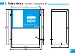
The mechanical components (rail, carriage, motor, supports, and sensors) are pre-mounted and must be
attached to the frame with screws. The frame is also prepared with rivet-down nuts.
Adjust the pneumatic nozzles and, if necessary, the high-pressure nozzles so that these end around 20 - 30
mm before the thermal mass.
Attention:
The nozzle stream must impinge perpendicular to the thermal mass!
Control whether the inductive proximity switches are correctly positioned. The metal vanes of the carriage
must be positioned around 2 mm away from the sensors. This requires adjusting the clamping block at the
end of the rail to loosen the toothed belt. After setting the position switches, position the cleaning carriage in
its centre position and tension the toothed belt again. For the correct connection of the centre and peripheral
sensors, an LED in the AS 2 control system lights up over the respective terminals on contact.
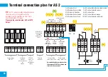
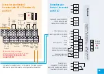
Connect the AS 2 control system according to the terminal plan.
Switch on the mains voltage.
Adjust the clock sensor on the periphery of the rotor. The clock sensor must receive one pulse per rotor
revolution. (sensing distance around 20 mm)
For commissioning, the cleaning control is equipped with three buttons:
Reset
(return to the start position),
Start
and
Stop
.
.


