Assembly and Repair Instructions
page 4 of 6
release 0
Chemoball KH2F-CI
file:
Montage-Reparatur-
Anl KH2F-CI_
EN-110429.doc
Provide: Roth/BNi
Printed pages will not be updated
Approval: Roth
Date: 29.04.2011
4
Assembly of the Chemoball KH2F-CI
4.1 Preparing
for
Assembly
All parts must be prepared to assemble the ball valve, i.e. the parts are carefully cleaned and laid on a soft base
(rubber mat or similar).
It must be considered that the plastic parts are almost always soft and very sensitive and that in particular the
sealing surfaces may not be damaged.
4.2
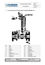
Assembling the Valve
The body (1) of the valve must be tensioned securely and safely in a suitable device; free access to the cavity
and stem must be guaranteed.
Before assembling, please take care that all components are clean and free of impurities.
Lightly grease the body (1) in the area of the seat ring with high temperature grease (e.g. Q1) licensed by the
FDA.
Insert seat ring (4) into bore. It should be able to insert it with slight manual pressure. If it fits too tightly or too
loosely the dimensions must be checked.
Similarly grease the cap (2) in the area of the seat ring and insert seat ring (4).
Thread on seal (7) and bearing ring (8) to stem (6).
Push on stem (6) from the inside through the body (1). Sealing parts may not be damaged.
Thread on packing rings (9), ring (10), thrust washer (11) and plate springs (12) from the top on the stem (6).
Tighten with hexagon nut (13) on block. Please take care, that the stem (6) must be locked from the body
side.
Insert the ball (3).
Insert body seal (5) into body (1).
Fit cap (2) carefully into body (1) without damaging the body seal (5).
Coat hexagon screws (21) on the thread with high temperature fat (OKS). Tighten hexagon screws (21)
crosswise gradually until the seal is evenly pressed out and cap (2) is metallically on block with body (1).
Thread on cover ring (14) and cover (15) to the stem (6). Tighten with allen screws (17). For DN 15 to DN 25
also stop pins (24) are inserted into the provided holes.
Push on stop plate (16).
Push on hand lever (19), push on allen screw (20) of the hand lever and tighten.
Thread on locking plate (22) and tighten with allen screw (23).
4.3
Function, Strength and Tightness Test
After assembling the ball valve it must be checked whether it can move freely and whether the ball can turn
unhampered. Finally the ball valve must be subjected to a strength and tightness test in accordance with
EN12266 -1 Nr. P10 / P11 / P12.

