Assembly and Repair Instructions
page 5 of 6
release 0
Chemoball KH2F-CI
file:
Montage-Reparatur-
Anl KH2F-CI_
EN-110429.doc
Provide: Roth/BNi
Printed pages will not be updated
Approval: Roth
Date: 29.04.2011
4.4
Independent Conversion and Manufacture of Spare Parts
Conversion while changing the valve is only permissible after agreement and written declaration by the
manufacturer. Original spare parts and accessories authorised by the manufacturer serve the purposes of safety.
If other spare parts are used and consequences result KLINGER SCHÖNEBERG GmbH shall not assume
liability.
4.5
Incorrect Operation
The operationally reliability of the valve is only guaranteed if it is used correctly in accordance with the operating
instructions for KLINGER SCHÖNEBERG ball valves. The limit value specified in the technical documentation
may under no circumstances be undercut.
5
Dismantling of the Chemoball KH2F-CI
5.1
Precautionary Measures
In order to ensure that any product residue which has remained in the cavity of the valve cannot lead to risk to the
staff performing the dismantling operation, appropriate protective clothing made of chemical and solvent resistant
material is to be worn on the entire body and a resistant facial protection.
For reasons of caution dismantling should be performed via a catch tank. Any toxic gases or vapours must be
extracted so that they may not reach personnel. This also applies to the final cleaning after dismantling has been
completed.
The ball valves must be brought into a pressure-free state for the purposes of repair. For this purpose they should
be brought into the semi-open position. It will similarly be necessary to perform cleaning on the inside and outside
before dismantling. It is expedient to switch the ball several times during cleaning of the cavity.
5.2 Preparing
for
Dismantling
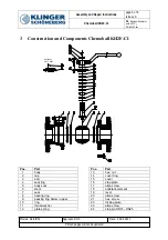
Before dismantling, the body (1), the cap (2) and the parts of the ball valve should be marked so that the
assembly positions can be understood later on.
5.3 Dismantling
For the purposes of dismantling the valve is tensioned again securely and safely in a suitable device. This is done
best on the flange of the body (1) in order to guarantee free access to the intermediate flange, cavity and stem.
Before starting dismantling, the ball valve must be closed.
Unscrew the allen screw (23) and remove the lever (19) and the locking plate (22).
Unscrew the hexagon screws (21) und remove the cap (2).
Take the ball (3) out of the body (1).
Remove the stop plate (16), unscrew the allen screws (17) and remove the cover (15).
Unscrew the hexagon nut (13). Please take care that the stem (6) is locked from the body side.
Plate springs (12), thrust washer (11), ring (10) and packing rings (9) can be removed.
Press the stem (5) from the top into the body and remove it.
Seal ring (7) and bearing ring (8) can be removed.
Seat rings (4) can be dismantled.
Finally the body seal (5) can be removed.


