Assembly and Repair Instructions
page 6 of 6
release 0
INTEC K411- T&L-STD
file:
Montage-Reparatur-
Anl INTE K411 T&L STD-
EN_22012016
Provide: Hauck
Approval: Roth
Printed pages will not be updated
Date: 22.01.2016
5.2
Preparing for Dismantling
Before dismantling, the body (1), the cap (2) and the parts of the ball valve should be marked so that the assem-
bly positions can be understood later on.
5.3
Dismantling
For the purposes of dismantling the valve is tensioned again securely and safely in a suitable device. Loosening
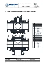
the hexagonal screws (18) will permit the cap (2) and blind cap (22) to be removed. Move the ball (3) to the open
position (two flat along the flow direction). Press ball (3) into the body (1) with suitable device, to lift the pre-load
from the ball seat (4). Therefore the trunnion can be removed. Remove the device and retain the ball.
After that the stem is dismantled. To unscrew the nut (14) you have to push a wedge into the slit of the nut. Using
a wrench, the nut (14) can be screwed from the stem (6) in anti-clockwise direction. The stem can now be careful-
ly pressed into the ball area. Secure the stem against falling down and damage.
The bearing (11) and below sealing parts (7) (8) can be removed form stem and upper sealing parts (9) (10) (12)
can be removed from the cone.
Then seat ring parts (4) (21) (19) can be dismantled. Finally the body seal (5) is removed. Auxiliary agents will
not usually be required.
5.4
Final Cleaning and Recording of Damage
After dismantling all parts are finally cleaned. The dismantled sealing parts are also to be included in cleaning so
that they may be disposed of with problem.
The damage is then recorded.
Special attention must be paid to inside and outside damage to the body parts. The nature of the sealing surfaces
at the ball seal, stem conduit, body sealing and the flange seals must be checked. The body parts are then jet-
cleaned inside and out with glass pearls and cleaned mechanically if necessary and possible. For this purpose
sealing areas must be covered up.
The valves are then to be cleaned anew and are then available for a further visual check for new assembly.
The stem is checked after visual checking for parallel running and traces of pressure of the two other flanges.
Special attention must be directed at the perfect state of the sealing areas. Slight scratches can be removed with
emery cloth. Damaged or twisted stems are replaced.
The cleaned ball is firstly visually checked. Deep scratches as well as other mechanical damage and chemical
attack on the sealing surface as well as the running surface of the seal ring mean that the ball must be discarded.
Similarly deformation in the area of the ball slit is inadmissible. All screws and sealing parts must be replaced
during every repair.

