Multiplexer
3 Multiplexer Hardware
A8
KLIPPEL Analyzer System
Page 5 of 16
Multiplexer Hardware
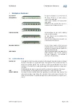
IN / OUTPUT
CONNECTORS
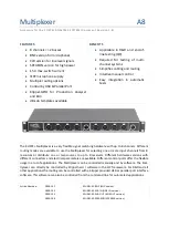
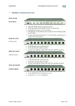
All signal connectors are at the front of
the device. There are no active compo-
nents in the signal path.
LINE version provides full symmetrical
signal paths.
SPEAKER version provides four wire con-
nections for each speaker channel.
RACK MOUNTING
The Multiplexer can be used as desktop
device or rack mounted.
19” Rack Mounts can be installed at the
front or backside.
Status LEDs and Manual mode switch are
on both sides of the device.
MANUAL CONTROL
An Up / Down Switch at the front and
backside allows to control the Multiplexer
manually. An external manual switch can
be connected optionally.
IEPE POWER
IEPE microphone supply is available at the
BNC multiplexer only. It can be switched
for bank 1 (channel 1 – 4) and bank 2
(channel 5 – 8) separately.
3.1
Control Interfaces
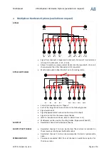
DIGITAL I/O
The Digital I/O interface can be connected to the Klippel Production Analyzer or Klippel
Analyzer 3 hardware or any parallel PC port. The Digital I/O Thru connectors allows to
daisy chain multiple devices. The connection is made by standardized 25 pin D-Sub
connectors. The interface is optically decoupled for a stabile operation in rough envi-
ronments.
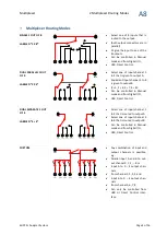
The Routing Modes have to be selected at DIP switches at the backside of the device.
USB
The USB interface is decoupled for a stabile operation in rough environments.
DIRECT CONTROL
The Direct Control interface offers the possibility to control each relay directly. The
wide control voltage range allows the connection from a wide range of devices. The
Direct Control interface is optically decoupled for a stabile operation in rough environ-
ments.

