background image


Klippel R&D System 

KCS-ID Manual  

  3 

Note:

 The current sense (Low/High Sense) is set automatically by the KCS-ID operation and does not 

have to be changed for the KCS-ID measurement. 


KA3 Signal Configuration


1.4


Performing Measurements 

1.4.1


Basic Measurement Setup 

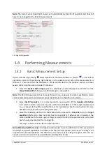
Open a database by pressing 


Select Database 

in the dB-Lab software. Create 

 a new 

KCS-ID


operation,  open  its 

Properties

  by  right-clicking  on  the  operation  and  set  up  the  measurement  as 

follows.  It  is  assumed  that  the  hardware  is  set  up  as  described  in  the  previous  section  and  laser 
sensor and microphone are connected to the KA3. 

1.


Select the 

Speaker System Type 

(

free air

sealed box

 or 

vented box

/

passive radiator

) and the 

Target Bandwidth

 (fullrange, woofer/midrange or subwoofer).  

Note:

 The KCS-ID measurement has to be performed in an enclosure of similar specification (same 

volume and same passive radiator/port properties) like used in the KCS on-line mode. 

2.


Select 

Limit  Parameters

.  It  is  recommended  to  never  switch  off  the 

Impulsive  Distortion


limit  which  indicates  excessive  impulsive  distortion  (

Rub&Buzz

).  If  the  target  displacement 

X

target

 is known, it should be specified here as limit parameter. See the next section for more 

detailed information about the limit parameters. 

3.


Select the hardware platform the initial data shall be created for. 

Only KA3

:

 Also, the 

Target 

amplifier

  (

AMP  card

  or 

External  amp

)  has  to  be  specified.  If 

External  amp

  is  selected,  the 

same amplifier with the same gain settings on which the KCS-ID measurement is performed 
has to be used as amplifier for running KCS. 

This step can also be done after the measurement. 

Note (KA3 target platform only

): It is highly recommended to use the AMP card for KCS evaluation if 

its voltage and power capabilities are sufficient for the particular speaker, because DC coupling is not 
supported on external amplifiers. The AMP card can provide a peak voltage of approx. 20 V and can 
handle a minimum load of 2 Ω (see specification [H6 Amplifier Card]) 

Summary of Contents for KCS-ID

Page 1: ...R D SYSTEM USER S GUIDE KCS ID Manual K l i p p e l G m b H July 23 2021 Copyright 2000 2021 Klippel GmbH Mendelssohnallee 30 01309 Dresden Germany www klippel de...

Page 2: ......

Page 3: ...urements 3 1 4 1 Basic Measurement Setup 3 1 4 2 Additional Options 4 1 4 3 Limit Parameters 4 1 4 4 Running and Interpreting Measurements 5 1 5 Creating Initial Data 7 1 6 Xmax and Xtarget 7 1 6 1 Wh...

Page 4: ......

Page 5: ...is initial data set is stored in a KCS Monitor operation and can be downloaded from the server The KCS Monitor operation can connect to any supported KCS hardware platform and a KCS control session ca...

Page 6: ...prises all relevant information required by KCS ID Make sure that IEPE phantom power is switched on using the buttons next to the microphone input on the KA3 s front panel If a transducer with multipl...

Page 7: ...like used in the KCS on line mode 2 Select Limit Parameters It is recommended to never switch off the Impulsive Distortion limit which indicates excessive impulsive distortion Rub Buzz If the target...

Page 8: ...have access to the transducer s membrane and cannot be used Note that a microphone calibration is not required for this measurement Advanced Save Intermediate Results saves the results of each measure...

Page 9: ...change the default impulsive distortion limits Note The IDR is very susceptible for impulsive distortion e g voice coil rubbing and not so much for air flow noises which exhibit less impulsive charact...

Page 10: ...t has successfully finished the measurement status overview in the State table displays a PASS after all measurement modes and an 8 character identification number Initial KCS data can now be created...

Page 11: ...tor KCS3 Before evaluating KCS it is highly recommended to see Tutorial 4 Alignment Equalization and 5 Protection Limiter of KCS3 which describe steps how to achieve best audio performance Note The ha...

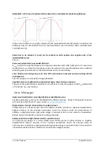
Page 12: ...which can cause an asymmetric peak excursion This means that for instance the positive peak displacement is higher than the absolute peak value on the negative side see curves below If the voice coil...

Page 13: ...multiple voice coils each driven by a separate amplifier channel Note KCS only supports multi coil configurations if all coils show identical small and large signal properties Please contact Klippel...

Page 14: ...INEAR MODE either the voice coil was shifted significantly due to very asymmetric nonlinear behavior of the transducer or the distance between laser sensor and transducer membrane position has changed...

Page 15: ...using a DC voltage Stabilization is not possible Note that KCS will work anyway but higher safety margins for the maximum allowed excursion are required leading to less acoustical output at low freque...

Page 16: ...educed The gain of the specified target amplifier is not sufficient to drive the speaker to the Xmax determined in the KCS ID Xmax was reduced Error Messages High Linear Identification error High Nonl...

Page 17: ...Setup Routing 2 How to achieve a higher Xmax 8 I Info Warning Messages 10 Introduction 1 K KCS Server messages 10 KCS ID Manual 1 KCS ID messages 10 L Limit Parameters 4 P Performing Measurements 3 R...

Reviews: