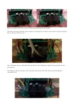
Reference: Switch contacts in blue, pots as red/green/purple, bracing mounts as yellow.
Note: Because these potentiometers will be mounted contacts away from the board, you will need to swap the red/purple
sides to maintain a clockwise action.
1. Solder new wiring to main PCB board.
Note: Unlike these pictures, make sure the wiring is kept as low and backward as possible to allow space for the new
potentiometers.
Note: Make sure that the wire doesn't poke through the opposite side of the PCB, otherwise it will be difficult to
reassemble the unit.
2. Surround solders with hot melt glue.


