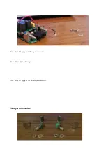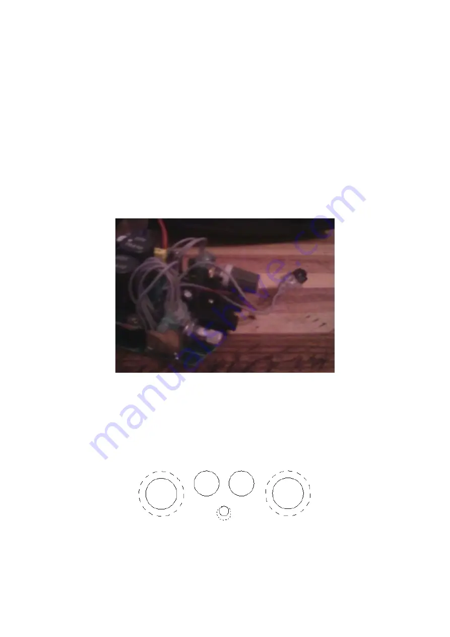
3. Solder wiring to potentiometers.
4. Attach potentiometers to frames.
Note: In this case I added some hot melt glue between the frames and potentiometers to prevent slipping.
5. Solder frames to main PCB.
New switch:
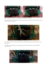
1. Sever the LED wiring. You could new wire for length, but if you cut close to the LED it shouldn't be
necessary.
2. Connect the two leads from the LED and the two leads from the old pot switch as per the switch wiring
schematic.
Faceplate modification:
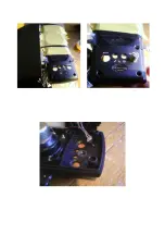
Information: the following picture shows the original faceplate holes in solid, and the new, larger holes in dash. The
original knobs have a diameter of ~9mm, these new parts ~12mm. The 2.5mm LED is replaced with a 4mm diameter-
bushed toggle switch. Since the LED hole is so close to the jacks, it is drilled with matching tops rather than matching
centres, so there is enough space for the toggle switch.


