background image

8

Klübermatic PRO

3.2 

Assembly of the Lubricator

a)

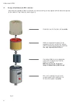
Insert the battery PRO B into the drive unit (according to the direction of the arrow on the label).

b)

3ODFHWKH352/&LQVLGHWKHSURWHFWLRQFRYHUDQGUHPRYHWKHSOXJRIWKH352/&UHIHUWR¿JXUH

¿JXUH

Protection cover

PRO LC

Plug

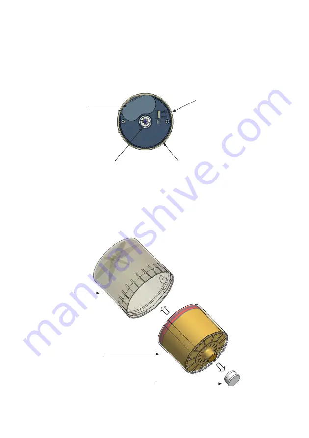
¿JXUH

1RIXQFWLRQ

Setting of PRO LC size is done via 
menu on display

Battery PRO B

Catch

Interlocking teeth

Summary of Contents for Klubermatic Distributor PRO MP-6

Page 1: ......

Page 2: ...as a result We will include any necessary changes in the next edition Compiled and printed 12 10 2020 Klübermatic PRO 250 500 1 20 Klübermatic PRO C 250 500 21 40 Klübermatic PRO PRO C LINE 250 500 41 44 Klübermatic Distributor PRO MP 6 45 61 Accessories and Spare Parts 62 63 Declaration of Conformity PRO PRO LINE PRO C PRO C LINE Distributor PRO MP 6 64 66 Drilling template 67 68 Klüber Lubricati...

Page 3: ...uring Operation 5 5 Switching the Lubrication System On 6ZLWFKLQJ WKH XEULFDWLRQ 6 VWHP 2ႇ 5 7 Determining the Discharge Period 5 8 Settings and Display for Klübermatic PRO 5 9 Calculation of the Remaining Discharge Period 6 Replacement of the PRO LC 17 6 1 Setting the Volume of the PRO LC 6 2 How to Replace the PRO LC 7 Trouble Shooting 19 7 1 Error Messages on the Display 7 2 Trouble Shooting Gu...

Page 4: ...tor PRO MP 6 45 Quick Reference Guide 47 1 General Information 48 1 1 Delivery Content 1 2 Markings 1 3 Intended Usage 2 Technical Data 49 2 1 Design of the Klübermatic Distributor PRO MP 6 2 2 Accessories 3 Mounting and Assembly of the Distributor 51 3 1 Mounting the Connections 3 2 Distributor Housing 3 3 Combination of Distributor and Lubricator 4 Operation and Control 54 4 1 Preparations 4 2 P...

Page 5: ... Distributor PRO MP 6 will either be called distributor or by its name Klübermatic MP 6 Battery PRO B In the following text battery PRO B will be called battery Usage of Safety Instructions All safety instructions in this operating manual are standardized Danger Signs This sign warns you of any danger to people s health or to subjects Tips This sign alerts you to application tips which will help y...

Page 6: ...igh pressures of up to 25 bar 360psi Only an original connecting cable from Klüber can be used to connect the lubricator PRO C to your control system and your equipment Ambient media especially chemically aggressive substances can attack seals and plastic Safety Information for Klübermatic PRO PRO C PRO PRO C LINE Distributor PRO MP 6 Safety during Installation and Maintenance QVXUH WKDW DOO ZRUNV...

Page 7: ...1 Klübermatic PRO 1 ...

Page 8: ... Push Button MODE SAVE Leads to the RQ JXUDWLRQ 0HQX DQG VDYHV the selected settings Drive Unit Contains electronics motor and pump system Battery Compartment For insertion of battery PRO B Catch For driving the spindle Interlocking Teeth To position the PRO LC No function Setting of PRO LC size is done via menu on the display Battery PRO B Config TimePIN Outlets 1 3 2 4 5 6 Days Weeks Months Vol L...

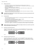
Page 9: ...d refer to chapter 5 7 Refer to the manufacturer s guidelines about the lubrication point that you want to lubricate in order to determine the required lubricant amount in cm3 per one hundred operating hours 5HIHU WR FKDUW FKDSWHU FKDUW DQG QG RXU UHTXLUHG OXEULFDWLRQ DPRXQW DVHG RQ WKDW WKH FKDUW will show you the required PRO LC size the setting of the discharge period and the setting mode Setti...

Page 10: ... and D or Non Hazardous Locations only Warning Explosions Hazard Substitution of components may impair suitability for Class I Division 2 7KH OXEULFDQWV GLVSHQVHG E WKLV HTXLSPHQW DUH WR KDYH À DVK SRLQWV JUHDWHU WKDQ Manufacturer perma tec GmbH Co KG Hammelburger Straße 21 97717 Euerdorf Germany Tel 49 0 9704 609 0 E mail info perma tec com Fax 49 0 9704 609 50 Web page www perma tec com 1 4 Inte...

Page 11: ...dashed line of the standard grease range at 3 m 2 You want to use a 4 m tube Up to which temperature can the system be used Correct Answer 10 C 50 F with standard grease 5 C 23 F with low temp grease arrow 3 meets the dotted line of low temp grease at the 5 C mark and the dashed line of the standard grease at the 10 C mark Klübermatic PRO 250 Klübermatic PRO 500 Volume of the PRO LC 250 cm3 500 cm...

Page 12: ...drive unit re usable PRO LC Lubrication Canister can be supplied as 250 cm3 and 500 cm3 versions with the lubricant requested by the customer Use only original Klüber PRO LC The battery PRO B is not rechargeable and must be changed every time the PRO LC is replaced Batteries can only be used once Usage of Klüber battery PRO B only Drive unit consisting of a gear motor a pump system and an electron...

Page 13: ...make sure that the lubrication points and the complete lubricant tube is pre lubricated with the same lubricant that is contained LQ WKH 352 RU WKDW O EHU Rႇ HUV D J OXEULFDWLRQ FDUWULGJH IRU PDQXDOO RSHUDWHG JUHDVH SUHVVHV with the requested lubricant Connect the lubricant tube connection G3 8 to the outlet of the drive unit and install the tube correctly EHWZHHQ WKH RXWOHW DQG WKH OXEULFDWLRQ SR...

Page 14: ...ve unit according to the direction of the arrow on the label b 3ODFH WKH 352 LQVLGH WKH SURWHFWLRQ FRYHU DQG UHPRYH WKH SOXJ RI WKH 352 UHIHU WR JXUH JXUH Protection cover PRO LC Plug JXUH 1R IXQFWLRQ Setting of PRO LC size is done via menu on display Battery PRO B Catch Interlocking teeth ...

Page 15: ...RPHV RXW RI WKH RSHQLQJ UHIHU WR JXUH d Place the PRO LC with its protection cover on the drive unit Make sure that the catch locks and that the WHHWK RI WKH 352 DQG WKH GULYH XQLW LQWHUORFN UHIHU WR JXUH DQG JXUH Turn the cover clockwise until the bayonet catch locks JXUH JXUH ...

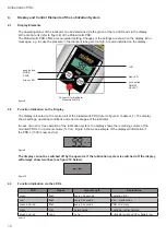
Page 16: ...f the lubricator In case of an error free operation of the lubrication system the display shows the remaining volume of the mounted PRO LC in percent volume Vol Figure 9 shows an example of the displayed information if the PRO LC 500 is new and full Vol LC 500 JXUH 7KH GLVSOD FDQQRW EH VZLWFKHG Rႇ E WKH RSHUDWRU I WKH OXEULFDWLRQ V VWHP LV VZLWFKHG Rႇ WKH GLVSOD ZLOO DOZD V VKRZ WZR OLQHV VHH JXUH...

Page 17: ...ently prelubricated with the same lubricant that the PRO LC contains For this Klüber offers a 400 g lubrication cartridge for grease presses with the corresponding lubricant refer to Accessories and Spare Parts When installing the Klübermatic PRO the supplied Klüber mounting device should be used The lubricant tube must be installed and mounted correctly The length of the lubricant tube may not ex...

Page 18: ...OLQJ OHYHO RI WKH WUDQVSDUHQW 352 UHJXODUO After one or several additional discharges you have to calculate the reduced discharge period and note this on your lubrication and maintenance schedule If a malfunction is indicated on the display you can determine the cause using the trouble shooting guide UHIHU WR FKDUW FKDSWHU I WKH IDXOW FDQQRW EH HG SOHDVH FRQWDFW RXU VXSSOLHU IRU WHFKQLFDO VXSSRUW ...

Page 19: ...e g weekends or annual holidays You should also note the result of your calculation of the remaining discharge period in your lubrication and maintenance schedule Average discharge volume in cm3 per 100 operating hours PRO LC 250 500 Setting mode Setting point Discharge period Days Weeks Months Days Weeks Months 1 1041 7 148 8 34 3 2083 3 297 6 68 5 2 520 8 74 4 17 1 1041 7 148 8 34 3 3 347 2 49 6...

Page 20: ... Time TimePIN Config Time Weeks Change Days or Weeks ON OFF SELECT Set discharge period Go to Days or Weeks MODE SAVE Config Outlets 1 3 2 4 5 6 2XWOHW 2Q 2ႇ ON OFF SELECT Activate outlets Activate outlet 1 Outlets only displayed if MP 6 is connected Outlets Config Outlets 1 3 2 4 5 6 Outlet 1 activated MODE SAVE Config Outlets 1 3 2 4 5 6 2XWOHW 2Q 2ႇ ON OFF SELECT Outlet 2 activated if desired other...

Page 21: ...splay settings can be saved with a long push of the MODE SAVE button If you do not want to save your FKDQJHV WR VHWWLQJV WKDW DUH FXUUHQWO GLVSOD HG LQ WKH FRQ JXUDWLRQ PHQX 7LPH 2XWOHWV 3 1 SUHVV WKH ON OFF SELECT button until the display shows either IRU 2ႇ RU WKH UHPDLQLQJ YROXPH RI WKH 352 LQ VOL All other settings and already saved changes remain valid XWRPDWLF 7HUPLQDWLRQ RI WKH RQ JXUDWLRQ ...

Page 22: ...S ZKHQ the system continues operation at a max of two additional discharges with every regular discharge 5 9 Calculation of the Remaining Discharge Period Please note that in case of one or several additional discharges the remaining discharge period of the lubrica WLRQ V VWHP PXVW EH UHFDOFXODWHG 7KLV DOVR DSSOLHV LQ FDVH RI D FXW Rႇ RI WKH OXEULFDWLRQ V VWHP GXH WR D ORQJ PDFKLQH VWDQGVWLOO H J ...

Page 23: ...against moisture an exchange may only be carried out in dry conditions After the installation of the new PRO LC the control system continues to operate using the previously valid setting of the discharge period 6 1 Setting the Volume of the PRO LC 7KH VL H RI WKH 352 PXVW EH VHW LQ WKH FRQ JXUDWLRQ PHQX ZLWK WKH WZR EXWWRQV RQ WKH GULYH XQLW VHH JXUH 3OHDVH DOVR UHIHU WR WKH RSHUDWLQJ FKDUW FKDUW ...

Page 24: ...WKH RSHQLQJ UHIHU WR JXUH chapter 3 2 g Place the new PRO LC on the drive unit turn it until the catch locks and the teeth of the PRO LC and the drive unit interlock The control system automatically recognizes the new PRO LC The display indicates if the Klübermatic PRO was VZLWFKHG R prior to the replacement of the PRO LC Or it indicates Vol if the Klübermatic PRO was switched on before the replac...

Page 25: ... point Excess motor current of the lubricator motor caused by a blocking of the displayed outlet Clear the blockage and ack nowledge the fault by pushing and holding down the ON OFF SELECT button E2 Lubrication system has been VZLWFKHG Rႇ Outlets of distributor not correctly recognized Replace distributor E3 Lubrication system has been VZLWFKHG Rႇ Timeout while activating distributor Connection ca...

Page 26: ...20 Klübermatic PRO 8 Disposal Help us in protecting the environment and saving resources by recycling valuable raw material Please follow your local waste disposal regulations ...

Page 27: ...21 Klübermatic PRO C 21 ...

Page 28: ...FDQW Red LED Additional malfunction indication Push Button MODE SAVE HDGV WR WKH RQ JXUDWLRQ 0HQX and saves the selected settings Drive Unit Contains electronics motor and pump system Connector Used for plugging in the connecting cable which connects the Klübermatic PRO C with the control system e g of a PLC 1 2 4 3 Battery Compartment For insertion of battery PRO B Catch For driving the spindle I...

Page 29: ...mount in cm3 per one hundred operating hours 5HIHU WR FKDUW FKDSWHU FKDUW DQG QG RXU UHTXLUHG OXEULFDWLRQ YROXPH DVHG RQ WKDW WKH FKDUW will show you the required PRO LC size the setting of the discharge period and the setting mode Setting of PRO LC Size Discharge Period Outlets and PIN refer to chapter 5 8 Hold down the MODE SAVE button until the set time is displayed Hold down the MODE SAVE butt...

Page 30: ...nd plug 4 until you are ready to install the system see chapter 5 2 1 3 Markings The lubricator Klübermatic PRO C is clearly marked with a label on the drive system serial number and a label on the PRO LC CE mark on the drive unit Manufacturer perma tec GmbH Co KG Hammelburger Straße 21 97717 Euerdorf Germany Tel 49 0 9704 609 0 E mail info perma tec com Fax 49 0 9704 609 50 Web page www perma tec...

Page 31: ...pendency of application temperature and tube length inner Ø 5 mm for Klüber standard grease and low temperature grease Temperature in F Application area for standard grease Application area for Low temp grease RXW RI VSHFL FDWLRQ UDQJH no warranty JXUH Klübermatic PRO C 250 Klübermatic PRO C 500 Volume of the PRO LC 250 cm3 500 cm3 Length L 210 mm 260 mm Diameter D 92 mm 92 mm Weight empty 1 30 kg...

Page 32: ... can be supplied as 250 cm3 and 500 cm3 versions with the lubricant requested by the customer Use only original Klüber PRO LC Drive unit consisting of a gear motor a pump system the connector for the connecting cable and an electronic unit for the control system re usable Connecting cable for linking the lubricator and the control system of your equipment e g a PLC JXUH The battery PRO B back up b...

Page 33: ... make sure that the lubrication points and the complete lubricant tube is pre lubricated with the same lubricant that is contained in the PRO RU WKDW O EHU Rႇ HUV D J OXEULFDWLRQ FDUWULGJH IRU PDQXDOO RSHUDWHG JUHDVH SUHVVHV ZLWK WKH requested lubricant Connect the lubricant tube connection G3 8 to the outlet of the drive unit and install the tube correctly EHWZHHQ WKH RXWOHW DQG WKH OXEULFDWLRQ S...

Page 34: ...the Lubricator a 3ODFH WKH 352 LQVLGH WKH SURWHFWLRQ FRYHU DQG UHPRYH WKH SOXJ RI WKH 352 UHIHU WR JXUH b 3XVK WKH 352 LQWR WKH SURWHFWLRQ FRYHU XQWLO OXEULFDQW FRPHV RXW RI WKH RSHQLQJ UHIHU WR JXUH JXUH Protection cover PRO LC Plug JXUH ...

Page 35: ... the control system e g a PLC of your equipment and SD DWWHQWLRQ WR WKH SLQ DVVLJQPHQW RI WKH FRQQHFWRU RQ WKH OXEULFDWRU UHIHU WR FKDUW DQG JXUH Insulate the connected strands correctly QVHUW WKH SROH FRQQHFWLQJ FDEOH LQWR WKH FRQQHFWRU RI WKH OXEULFDWRU UHIHU WR JXUH Screw tight the connector socket of the connecting to the connector of the lubricator Pin no of the connector on the lubricator St...

Page 36: ... in percent volume Vol Figure 9 shows an example of the displayed information if the PRO LC 500 is new and full Vol LC 500 JXUH 7KH GLVSOD FDQQRW EH WXUQHG Rႇ ZKHQ D 352 LV DWWDFKHG DQG D EDWWHU 352 EDFN XS EDWWHU LV LQVHUWHG I WKH OXEULFDWLRQ V VWHP LV VZLWFKHG Rႇ WKH GLVSOD ZLOO DOZD V VKRZ WZR OLQHV VHH JXUH below JXUH 4 3 Function Indication via the LEDs LED Signal Signal Length Explanation gr...

Page 37: ...rectly The length of the lubricant tube may not exceed a maximum of 5 meters and the tube must be a Klüber product Please check if the thread of the Klübermatic PRO C G3 8 corresponds to the connection thread of the lubrication point If this is not the case you can order a corresponding reducer or other parts from the Klüber accessory line XULQJ LQLWLDO RSHUDWLRQ WKH O EHUPDWLF 352 GULYH LV OOHG Z...

Page 38: ...onal discharges you have to calculate the reduced discharge period and note this on your lubrication and maintenance schedule If your control system indicates a malfunction you have to determine its cause directly via the display of the Klübermatic PRO C You can check for possible causes using the trouble shooting guide refer to chart 8 FKDSWHU I WKH IDXOW FDQQRW EH HG SOHDVH FRQWDFW RXU ORFDO VXS...

Page 39: ...4 4 17 1 5 208 3 29 8 6 9 416 7 59 5 13 7 6 173 6 24 8 5 7 347 2 49 6 11 4 7 148 8 21 3 4 9 297 6 42 5 9 8 8 130 2 18 6 4 3 260 4 37 2 8 6 9 115 7 16 5 3 8 231 5 33 1 7 6 10 104 2 14 9 3 4 208 3 29 8 6 9 11 94 7 13 5 3 1 189 4 27 1 6 2 12 86 8 12 4 2 9 173 6 24 8 5 7 13 80 1 11 4 2 6 160 3 22 9 5 3 14 74 4 10 6 2 4 148 8 21 3 4 9 15 69 4 9 9 2 3 138 9 19 8 4 6 16 65 1 9 3 2 1 130 2 18 6 4 3 17 61 ...

Page 40: ... 6 Days Weeks Months Vol LC2500 LC2500 Config Time TimePIN Config Time Weeks Change days or weeks SELECT Set discharge period Go to Days or Weeks MODE SAVE Config Outlets 1 3 2 4 5 6 2XWOHW 2Q 2ႇ SELECT Activate outlets Activate outlet 1 Outlets only displayed if MP 6 is connected Outlets Config Outlets 1 3 2 4 5 6 Outlet 1 activated MODE SAVE Config Outlets 1 3 2 4 5 6 2XWOHW 2Q 2ႇ SELECT Outlet 2 act...

Page 41: ...s back on All other settings remain unchanged Save or Reject Changed Settings The display settings can be saved with a long push of the MODE SAVE button If you do not want to save RXU FKDQJHV WR VHWWLQJ WKDW DUH FXUUHQWO GLVSOD HG LQ WKH FRQ JXUDWLRQ PHQX 7LPH 2XWOHWV 3 1 press the SELECT button until the display shows either IRU 2ႇ RU WKH UHPDLQLQJ YROXPH RI WKH 352 in VOL All other settings and ...

Page 42: ...ge Period Please note that in case of one or several additional discharges the remaining discharge period of the lubrica WLRQ V VWHP PXVW EH UHFDOFXODWHG 7KLV DOVR DSSOLHV LQ FDVH RI D FXW Rႇ RI WKH OXEULFDWLRQ V VWHP GXH WR D ORQJ PDFKLQH VWDQGVWLOO H J ZHHNHQGV RU DQQXDO KROLGD V RU LQ FDVH RI D ORZ WHPSHUDWXUH FXW Rႇ FDUULHG RXW E WKH system if temperatures reach 20 C 4 F You should also note t...

Page 43: ...e Klübermatic PRO C lubricator via your control system you need to set the lubricator WR LPSXOVH PRGH YLD WKH FRQ JXUDWLRQ PHQX UHIHU WR FKDSWHU For this you have to select the setting D V LQ WKH VHWWLQJ PRGH D V UHIHU WR JXUH 88 Outlets 1 3 2 4 5 6 Days Weeks Months Vol LC2500 LC2500 Config Time TimePIN Config Time Days JXUH 6 Replacement of the PRO LC The Following Must Always Be Taken into Accoun...

Page 44: ...icates and the red LED is blinking c Use battery PRO B until display shows Lo see chapt 7 d 5HPRYH WKH SOXJ RI WKH 352 UHIHU WR JXUH FKDSWHU e Push the PRO LC into the protection cover until lubricant comes out of the opening UHIHU WR JXUH FKDSWHU f Place a new PRO LC on the drive unit turn it until the catch locks and the teeth of the PRO LC and the drive unit interlock The control system of the ...

Page 45: ...or motor due to a blocked outlet Clear the blockage and acknowledge the fault by pushing and holding down the SELECT button E4 XEULFDWRU KDV EHHQ VZLWFKHG Rႇ Drive mechanism is defective Exchange the drive unit LC System does not detect the PRO LC No PRO LC installed Install an PRO LC L green LED blinking Low voltage of back up battery lubrication system functions correctly Battery PRO B back up b...

Page 46: ...40 Klübermatic PRO C 8 Disposal Help us in protecting the environment and saving resources by recycling valuable raw material Please follow your local waste disposal regulations ...

Page 47: ...Klübermatic PRO PRO C LINE 41 41 ...

Page 48: ...ch outlet The total discharge period changes whenever any of these values changes Whenever the selected settings would lead to an exceeded total discharge period the system shows You can either change the settings 1 or you can override 2 1 To change your settings 3XVK 21 2 6 7 RU 6 7 7KH V VWHP ZLOO UHWXUQ WR WKH FRQ JXUDWLRQ menu without saving the selected settings and you can change your settin...

Page 49: ...DPH ZD MODE SAVE Config Outlets 1 3 2 4 5 6 Changing the number of strokes ON OFF SELECT SELECT Enter number of strokes for outlet 1 Strokes MODE SAVE 88 Outlets 1 3 2 4 5 6 Days Weeks Months Vol LC2500 LC2500 Config Time TimePIN Config Time Outlets 1 3 2 4 5 6 Days Change UVW GLJLW ON OFF SELECT SELECT 3DXVH WLPH FRQ JXUDWLRQ for outlet 1 KDQJLQJ WKH UVW GLJLW Pause time MODE SAVE MODE SAVE 88 Outle...

Page 50: ...Klübermatic PRO PRO C LINE 44 ...

Page 51: ...Klübermatic Distributor PRO MP 6 45 45 ...

Page 52: ...drive unit and distribution system Connection thread for attaching a lubricator of the Klübermatic PRO range Outlets 4 to 6 with connections for grease lines Connector shown with its protective cap used for plugging in the connecting cable Plug 4 pcs for sealing the outlets that are not used Connecting cable 1 pc used for power supply and for communication 6 connections straight or angle for greas...

Page 53: ...ecting pieces of the distributor and lay them between the distributor and the lubrication point Connect the lubricator with the distributor using the connecting cable For this the lubrication system must EH VZLWFKHG Rႇ Determine Discharge Period refer to chapter 4 7 Determine the required lubricant volume cm3 per one hundred operating hours while taking into account the number of open outlets For ...

Page 54: ...ay only be used together with a lubricator of the Klübermatic PRO range must be connected to the lubricator using the connecting cable immediately supplies up to six lubrication points with lubricant at a pressure build up of max 25 bar 360 psi constantly precisely and independent of temperature has passed the environmental audit according to standard EN 60068 2 6 vibration test without any compon...

Page 55: ...lubricator via connecting cable Emission sound pressure level 70 dB A Connection thread for lubricators of the Klübermatic PRO range G3 8 inside Connection thread for grease line G1 8 inside Diameter of grease line 8 x 1 5 inner Ø 5 mm Length of the grease line admissible total length per pipe up to 5 m for details please regard operating manual Klübermatic PRO PRO C chapter 2 chart 1 Storage cond...

Page 56: ... the distributor to a lubricator of the Klübermatic PRO range The Klübermatic distributor MP 6 consists of Housing containing the drive unit and the distribution system max 6 outlets JXUH 2 2 Accessories Connections 6 pcs for grease lines Plugs 4 pcs for sealing the outlets which are not used Connecting cable short for power supply of the distributor and for communication between distributor and l...

Page 57: ... and the position of the outlets that you intend to use 6FUHZ WKH FRQQHFWLRQV WLJKWO PD WRUTXH RI 1P LQWR WKH RXWOHWV WR EH RSHQHG UHIHU WR JXUH Seal all the remaining outlets using the enclosed plugs 3 2 Distributor Housing Never loosen these screws at the bottom of the distributor and never open the housing JXUH JXUH 4 5 6 1 2 3 ...

Page 58: ...g device to the distributor and the lubricator using the enclosed hex head bolts M6 x 16 and the washers Screw the mounting device together with the lubrication system onto a support of your system RU WKH SRVLWLRQ RI WKH ERUHV RI WKH IRXU LQJ VFUHZV UHIHU WR JXUH EHORZ RX KDYH WR XVH IRXU KH DJRQ screws M6 x 25 e g on metal ground Connect the grease lines to the connections of the distributor and ...

Page 59: ... 8 female to G1 8 female for tube oØ 8 mm nickel plated Art No 101545 and the tube connector G1 8 male for tube oØ 8 mm straight brass nickel plated Art No 101570 on the lubri cator Fit the tube connector G3 8 male for tube oØ 8 mm straight brass nickel plated Art No 101498 on the distributor Connect the distributor to the PRO lubricator with the grease line Maximum tube length 2 meters Ø 8 x 1 5 ...

Page 60: ...OXEULFDWLRQ V VWHP IRU REYLRXV GDPDJHV LG RX FRUUHFWO DVVHPEOH PRXQW DQG WLJKWHQ DOO RI WKH FRQQHFWLRQV DQG WKH SOXJV RI WKH GLVWULEXWRU UH WKH JUHDVH OLQHV FRPLQJ IURP WKH GLVWULEXWRU PRXQWHG FRUUHFWO RQ WKH FRQQHFWLRQV Was the drive unit of the lubricator set to the discharge period requested by the operator while taking into DFFRXQW WKH UHTXLUHG GLVFKDUJH YROXPH DQG WKH QXPEHU RI RSHQ RXWOHWV L...

Page 61: ...blinks and the display shows the outlets squares the remaining volume in percent and the PRO LC size 250 and 500 cm3 Only with PRO The lubrication system is VZLWFKHG Rႇ Initialization process The lubrication system is on Outlets 1 3 2 4 5 6 Outlets 1 3 2 4 5 6 Vol LC 500 ON OFF SELECT JXUH KHQ WKH OXEULFDWLRQ V VWHP LV VZLWFKHG RQ IRU WKH UVW WLPH WKH LQLWLDOL DWLRQ LV FDUULHG RXW DXWRPDWLFDOO by ...

Page 62: ...ECT MODE SAVE PRO C SELECT MODE SAVE JXUH RU DQ DGGLWLRQDO GLVFKDUJH SUHVV ERWK EXWWRQV RI WKH OXEULFDWRU DQG KROG WKHP GRZQ An additional discharge is only possible at temperatures DERYH Every additional discharge reduces the remaining discharge period since an increased amount of the lubricant has been supplied This must be taken into account in your lubrication and maintenance schedule The time...

Page 63: ...Days Weeks Months Vol LC2500 LC2500 Config Time TimePIN Config Outlets 1 3 2 4 5 6 Activation Outlet 5 or SELECT ON OFF SELECT Activation of outlet 5 MODE SAVE 88 Outlets 1 3 2 4 5 6 Days Weeks Months Vol LC2500 LC2500 Config Time TimePIN Config Outlets 1 3 2 4 5 6 Outlet 5 active Outlet 6 inactive MODE SAVE 2XWOHW FRQ JXUDWLRQ QLVKHG chart 2 Caption Function Short push Long push Blinking in Display S...

Page 64: ...OFF PRO ZLOO LPPHGLDWHO VWDUW LQLWLDOL DWLRQ UHIHU WR JXUH PRO C will show a blinking in the display for the triggered initialization the actual initialization will be carried RXW DV VRRQ DV WKH V VWHP LV WXUQHG 21 UHIHU WR JXUH PRO ON OFF SELECT MODE SAVE PRO C SELECT MODE SAVE JXUH RU D PDQXDO LQLWLDOL DWLRQ SUHVV DQG KROG GRZQ ERWK EXWWRQV RI WKH OXEULFDWRU VLPXOWDQHRXVO Lubricator PRO When the...

Page 65: ...Ä FRQ UPDWLRQ V 6WDUWLQJ WKH 3URFHVV RI 3UH OOLQJ 1 7 3UH OOLQJ 1 7 RI WKH GLVWULEXWRU 03 ZLOO VWDUW ZKHQ Klübermatic PRO MP 6 is turned on or for Klübermatic PRO C MP 6 when power is applied The display will show DQG WKH RXWOHWV DFWLYH RXWOHWV EODFN ER RXWOHW ZKLFK LV EHLQJ OOHG ZLOO EOLQN OO DFWLYH RXWOHWV ZLOO JHW SUH OOHG 88 Outlets 1 3 2 4 5 6 Days Weeks Months Vol LC2500 LC2500 Config Time Ti...

Page 66: ... System gets no power from internal back up battery Internal back up battery empty Replace the drive unit of the lubricator No display for PRO C System gets no power from the back up battery No battery PRO B back up battery inserted Insert battery PRO B back up battery chart 3 5 Trouble Shooting 5 1 Error Messages of the Distributor on the Display of the Lubricator Possible errors of the distribut...

Page 67: ...rmatic Distributor PRO MP 6 61 6 Disposal Help us in protecting the environment and saving resources by recycling valuable raw material Please follow the individual waste disposal regulations in your country ...

Page 68: ...nts This is always guaranteed with genuine spare parts and accessories from Klüber Spare parts Illustration KM PRO LC 250 OOHG ZLWK OXEULFDQW KM PRO LC 500 OOHG ZLWK OXEULFDQW KM PRO Cover for LC 250 made of transparent plastic KM KM PRO Cover for LC 250 made of aluminium for applications with ester containing lubricants KM PRO Cover for LC 500 made of transparent plastic KM KM PRO Cover for LC 50...

Page 69: ...traight brass nickel plated max 7 5 mm KM Tube connector G1 8 male for tube oØ 8 mm 90 rotary type brass nickel plated max 7 5 mm KM PRO MP 6 Connecting cable 14 cm 0 UHDVH FDUWULGJH J OOHG ZLWK OXEULFDQW WR EH XVHG IRU SUH OOLQJ JUHDVH lines with a grease gun KM Tube up to 100 C oØ 8 mm x iØ 5 mm PA IRU 352 ZLWK GLႇ HUHQW OHQJWKV KM PRO Protection box single steel KM PRO Protection box double ste...

Page 70: ...designato nei modelli consegnati è conforme alle disposizioni delle norme sopra ripor tate incluse le variazioni valide al momento della dichiarazione In der Gemeinschaft ansässige Person die bevollmächtigt ist die relevanten technischen Unterlagen zusammen zustellen Person residing within the Community authorised to compile the relevant technical documentation Personne établie dans la Communauté ...

Page 71: ...ara che il prodotto designato nei modelli consegnati è conforme alle disposizioni delle norme sopra ripor tate incluse le variazioni valide al momento della dichiarazione In der Gemeinschaft ansässige Person die bevollmächtigt ist die relevanten technischen Unterlagen zusammen zustellen Person residing within the Community authorised to compile the relevant technical documentation Personne établie...

Page 72: ...o designato nei modelli consegnati è conforme alle disposizioni delle norme sopra ripor tate incluse le variazioni valide al momento della dichiarazione In der Gemeinschaft ansässige Person die bevollmächtigt ist die relevanten technischen Unterlagen zusammen zustellen Person residing within the Community authorised to compile the relevant technical documentation Personne établie dans la Communaut...

Page 73: ...67 Drilling template Drilling template Klübermatic Distributor PRO MP 6 45 ...

Page 74: ...Drilling template 68 45 75 66 5 6 5 Drilling template Screws M6 2x Fasting points 3x Fasting points ...

Page 75: ...12 10 2020 A01 en Art No 109501 ...

Page 76: ... BS MC BNMRTKS SHNM VD GDKO NTQ BTRSNLDQR SN AD RTBBDRRETK VNQKCVHCD HM KK HMCTRSQHDR MC L QJDSR 6HSG NTQŰ LAHSHNTR SDBGMHB K BNMBDOSR MC DWODQHDMBDC BNLODSDMS RS EE VD G UD ADDM ETKjKKHMF HMBQD RHMFKX CDL MCHMF QDPTHQDLDMSR AX L MTE BSTQHMF DEjBHDMS GHFG ODQENQL MBD KTAQHB MSR ENQ LNQD SG M XD QR www klueber com ...

Reviews: