


4IN. x 36IN. BELT/6IN. DISC SANDER
OWNER’S MANUAL
2 of 7
TOOL USE SAFETY
•
Know your tool.
Learn the tool’s operation, application and
specific limitations.
•
Use clamps (not included) or other practical means to
secure and support the workpiece to a stable platform.
Holding the work by hand or against your body is unstable
and may lead to lose of control.
•
Do not force the tool. Use the correct tool for your applica
tion.
The correct tool will do the job better and more safely
when it is used for the application it was designed for.
•
Do not use the power tool with a malfunctioning power
switch.
Any tool that cannot be controlled with the power
switch is dangerous and must be repaired by a qualified
technician.
•
Avoid accidental start-up.
Make sure that the tool is in the
“OFF” position before plugging in.
•
Disconnect tool before making any adjustments, changing
accessories, or storing the tool.
•
Never leave tool running unattended.
Turn the power off
and do not leave tool until it comes to a complete stop.
•
Do not overreach.
Keep proper footing and balance.
•
Never stand on tool.
Serious injury could occur if tool is
tipped or if belt or disc are unintentionally contacted.
•
Keep hands away from moving parts and sanding surfaces.
•
Keep extension cords off the ground and away from water.
•
Use recommended accessories.
Accessories designed for
one tool may be hazardous when used on another. Use of
improper accessories may cause risk of injury to persons.
•
Turn machine off if it jams.
Belt jams when it digs too deeply
into workpiece. (Motor force keeps it stuck in the work.)
•
Support a workpiece
with miter gauge, belt platen or work
table.
UNPACKAGING
WARNING:
Do not operate machine until completely
assembled. Do not operate machine until you have
completely read and understood this manual.
When unpacking, check for shipping damage and make sure
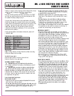
that the following parts are included:
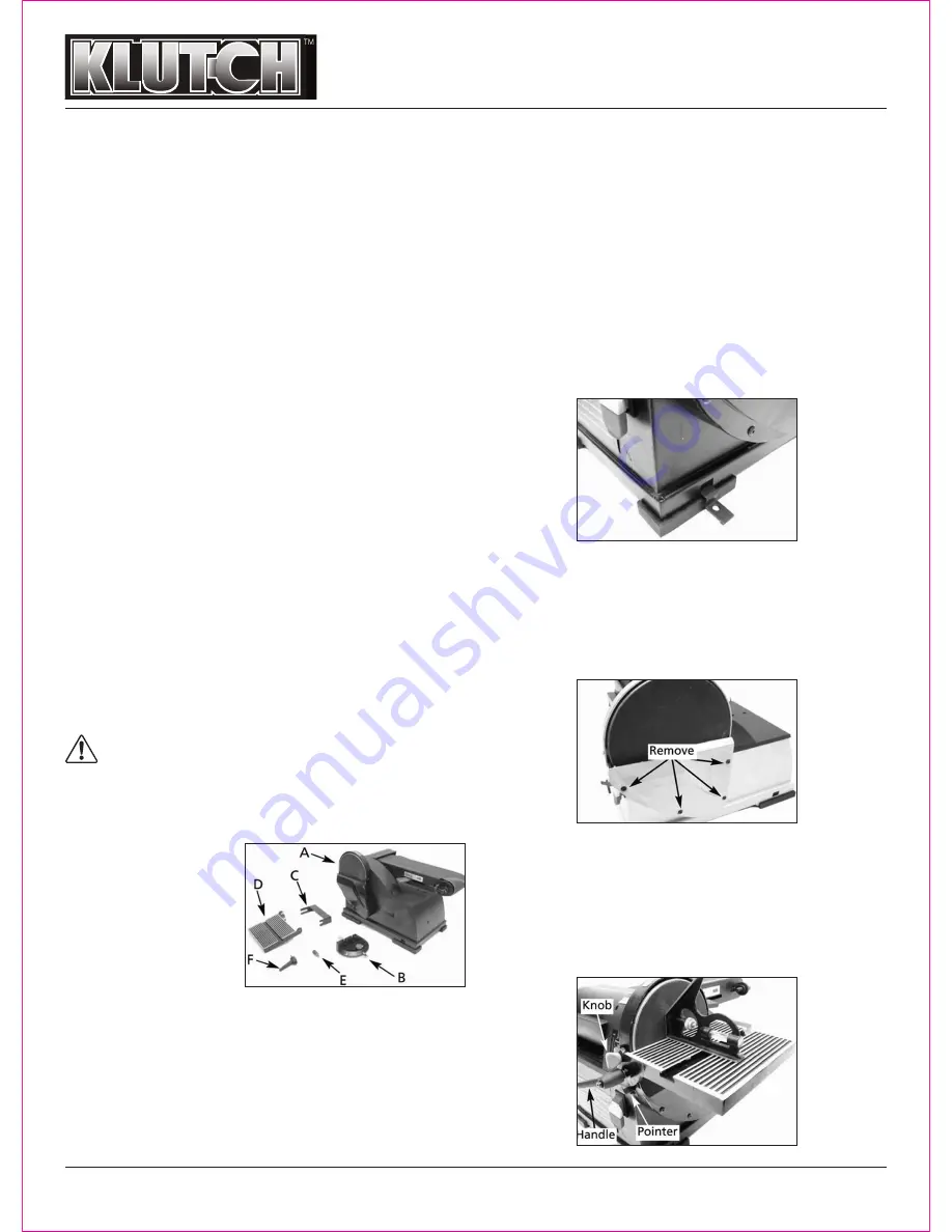
A. Sander
B. Miter Gauge Assembly
C. Back stop
D. Table
E. Stud
F. Locking Handle
Not shown:
Abrasive Disc Knobs
4 Feet 4 Mounting Brackets
2 M6X16 Socket Head Bolts 4 M6X16 Hex Head Bolts
2 M6 Lock Washers 6 M6 Flat Washers
4 M6 Hex Nuts Hex Wrench and Open Wrench
4 M6 Hex 6 M6 flat washer 4 M6 hex nut
While assembling or adjusting your belt and disc sander, you
will need the following tools:
13mm Wrench
3 and 5mm Hex Wrenches
Combination Square
Phillips Screwdriver
ASSEMBLY INSTRUCTIONS
MOUNT SANDER
Make sure there is plenty of room for installing and allow for
table assembly and belt assembly in horizontal position.
• The sander must be bolted to a firm, level surface.
• Find the 4 rubber feet in the parts bag, press a foot onto
each corner of the base of the sander..
• Press-fit each Rubber Foot over the lip of the Base corner.
• The Sander can be installed on a workbench or a tool stand
using bolts, lock washers, hex nuts and mounting brackets.
ATTACH ABRASIVE DISC
• Remove the Disc Cover by loosening and removing the four
screws.
• Peel the protective paper from the back of the Abrasive Disc.
• Center the Abrasive Disc on to the Aluminum Disc and press
it on firmly and evenly.
• Replace the Disc Cover.
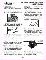
TABLE INSTALLATION
The included table is used with both the disc and belt.
• Position the Table on the Disc Guard and attach it using the
Knobs.
• Thread the Locking Handle through the Table and in to the
Disc Guard.
• Using a combination square, set the table perpendicular to
the Disc and secure in position. If necessary, set the Pointer
at 0º.


