background image

PWR

           KMB systems

1. Basic features

Main advantage of PWR power supplies are high over-voltage category (300V/CAT IV) and wide range of

supply voltage. PWR 1 unit can be powered using single phase AC or DC voltage and PWR 3 using
three phase AC voltage.

Power supply features indication of input voltage and protection against over-voltage. Even under over-

voltage conditions power supply can be operated with limited output power. (see chapters bellow)

PWR have galvanically isolated SELV output. Multiple power supplies can be connected as follows:

• 

parallel: 2× higher output current, more then 2 of same type can be connected (consult with KMB)

• 

parallel: redundant connection with benefit of higher reliability

• 

serial: 2× higher output voltage

• 

serial with central tap: result is power supply with symmetrical output voltage (+/-)

Power supplies have U-I characteristic – from voltage stabilisation smoothly transfers to current limitation

(limitation of maximal output current).

Internal over-voltage protection of input and output is implemented. Short-circuit protection, overload and

load disconnection protection is matter of course.

Operation of the PWR unit and status of external accu. is signalled by LED and SSR output.
Supplies with external accu. Have protection against wrong connection of the accumulator and against

total discharge of accumulator.

Cooling is provided by natural flow of the air. Fan-less.

2. Safety instructions

 Danger of electric shock! Do not open the device.
 Follow the operating instructions.

• 

Keep the operating instructions together with the device.

• 

Ensure that the device works only in perfect and original condition, in the upright position.

• 

Leave enough space (at least 50mm) for airflow below and above the device.

• 

Do not place heat sources under the unit!

• 

Do not use the device in an explosive areas.

• 

Ensure that only qualified persons operate the unit

• 

Only connections in this manual is permitted

• 

Only connect recommended external batteries or contact the manufacturer.

• 

Ensure that the device is not operating outside the limits. See technical data.

• 

Clean the machine only with a dry cloth or brush so that air vents remain clean.

 If the device is used in a manner other than that specified by the manufacturer, the device protection

may be compromised.

 Device may be repaired only by the manufacturer or its authorized service organization.

3. Risk assessment (ČSN EN 61010-1)

Requirements:

The dielectric strength to be met is 300V CAT IV. This corresponds to a test voltage of 5.4 kV ~ (5 s)
resp. 3kV ~ (1min) for reinforced insulation according to ČSN EN 61010-1.

Power Module Features:

Insulation voltage is 3kV ~ (1min), overvoltage category is 300V CAT II.

Operational risk without further action:

2

Summary of Contents for PWR 1A 60W 24V

Page 1: ...this manual may not always contain the latest information In this case please contact us or use the latest version of the operating instructions available on our website http www kmb cz Scope of delivery PWR unit including connector Operating Instructions Warranty card Certificates Optional accessories external battery CTL 7 12 12V 7Ah lifetime 10 years circuit breaker fuse switch OPVP10 OEZ 41013...

Page 2: ...tion against wrong connection of the accumulator and against total discharge of accumulator Cooling is provided by natural flow of the air Fan less 2 Safety instructions Danger of electric shock Do not open the device Follow the operating instructions Keep the operating instructions together with the device Ensure that the device works only in perfect and original condition in the upright position...

Page 3: ...rotection anti ingress of objects larger than 12 5mm without water protection This product must not be disposed of in a household waste bin but must be disposed of in such a way as to ensure its environmentally friendly recycling Alternating voltage AC direct voltage DC 5 Installation The person installing the system is responsible for safety of whole system containing the PWR Installation PWR is ...

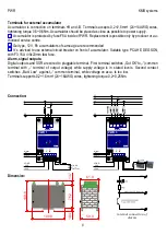
Page 4: ...outputs and SSR are wired to pluggable terminal First terminal switches Out OK to common terminal with terminal of output voltage while supply voltage is in stated levels Second contact switches Batt Low against common terminal while voltage on accu Is too low Terminals supports 0 2 1 5mm2 24 16AWG wires tightening torque 0 2 0 25Nm Connection Dimension 4 internal connection of alarms 109 8 59 0 1...

Page 5: ... limited to 0 75A Output voltage is based on charge level of accumulator see charts Operator have to Operator must ensure that drawn power don t cross limits stated in thermal chart This model can be operated also without accumulator In such a case output voltage will be equal to max imal voltage of the output see specifications Operation of PWR from line to line voltage in 3 400 230V networks onl...

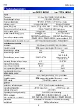
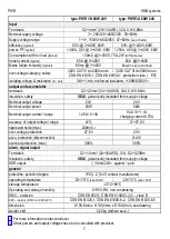
Page 6: ...y SELV galvanically insulated from supply voltage Nominal output voltage 24V 24V Nominal output power 60W 60W Nominal output current range 2 5A 0 3 75A 1 4A 0 2 2A charging current 0 75A total current 3 0A accuracy of output voltage range 1 21 27 6V ripple and noise max 240mVP P over voltage protection 27 6V 29V accu protection disconnection 21 1V overload protection max 150 150 alarm signal outpu...

Page 7: ...y voltage Nominal output voltage 24V 24V Nominal output power 60W 60W Nominal output current range 1 45A 0 3A 0 4A 0 1 1A charging current 0 75A accuracy of output voltage range 1 21 27 6V ripple and noise max 240mVP P over voltage protection 27 6V 29V accu protection disconnection 21 1V overload protection max 300 300 alarm signal output Terminals 0 2 1 5mm2 24 16AWG 12A 0 2 0 25Nm Insulation saf...

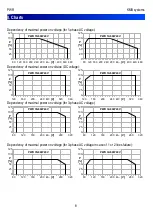
Page 8: ...40 480 0 25 50 75 100 125 PWR 1N 60W 24V U V P 80 120 160 200 240 280 320 360 400 440 480 0 25 50 75 100 125 PWR 1A 60W 24V U V P 120 160 200 240 280 320 360 0 25 50 75 100 125 PWR 1N 60W 24V U V P 120 160 200 240 280 320 360 0 25 50 75 100 125 PWR 1A 60W 24V U V P 80 120 160 200 240 280 320 0 25 50 75 100 125 PWR 3N 60W 24V U V P 80 120 160 200 240 280 320 0 25 50 75 100 125 PWR 3A 60W 24V U V P ...

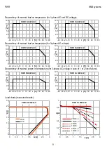
Page 9: ...2 2 5 3 0 0 2 0 4 0 6 0 8 1 PWR 1A 60W 24V 230 23 3 120 23 3 230 25 120 25 230 27 2 120 27 2 Iz A Ia A 40 30 20 10 0 10 20 30 40 50 60 70 80 0 25 50 75 100 125 PWR 1N 60W 24V t C P 40 30 20 10 0 10 20 30 40 50 60 70 80 0 25 50 75 100 125 PWR 1A 60W 24V t C P 40 30 20 10 0 10 20 30 40 50 60 70 80 0 25 50 75 100 125 PWR 3N 60W 24V t C P 40 30 20 10 0 10 20 30 40 50 60 70 80 0 25 50 75 100 125 PWR 3A...

Page 10: ... a product failure a claim must be made with the supplier or the manufacturer at KMB systems s r o Dr M Horákové 559 460 06 Liberec 7 tel 420 485 130 314 fax 420 482 736 896 e mail kmb kmb cz internet www kmb cz The product must be properly packed in such a way as to avoid damage during transport The product must be provided with a description of the defect her speech Entitlement to warranty servi...

Reviews: